HanRun HR601680 Alternative: VOOHU WHS16013LF Comparison
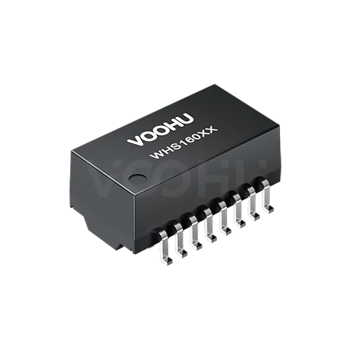
The VOOHU WHS16013LF is a functional alternative to the HanRun HR601680 — verify with samples in your design. Both are 16-pin, 1.27 mm pitch surface-mount LAN transformers for a single 10/100 Ethernet port, with 1CT:1CT windings, 350 µH minimum OCL under 8 mA DC bias, 1500 V isolation for 60 seconds and a 0 to +70 °C operating range. On both datasheets, pins 1–8 face the PHY and pins 9–16 face the cable. The two things to check are the outline and the land pattern: the WHS16013LF body is 12.80 ± 0.50 mm long against 0.500 in (12.70 mm) max for the HR601680, and the recommended pads are sized differently. Order samples of the WHS16013LF and our FAE team can check both points against your board.
产品WHS16013LF
HR601680 datasheet values next to the WHS16013LF
Every value below is copied from the two published datasheets: HanRun HR601680 Rev B and VOOHU WHS16013LF Rev A0. HanRun gives its mechanical dimensions in inches; the millimetre figures in brackets are conversions for easier reading. Where a datasheet does not list an item, the cell says "not stated".
| Parameter | HanRun HR601680 (source) | VOOHU WHS16013LF (source) |
|---|---|---|
| Application | 10/100BASE-T, single port (DS p1) | 10/100BASE-TX, single port (DS p1) |
| Pins / pitch | 16 / 0.050 in [1.27 mm] (DS p1) | 16 / 1.27 ± 0.20 mm (DS p1) |
| Chip-side pins | Transmit 1-2-3, center tap 2; receive 6-7-8, center tap 7 (DS p1 schematic) | TD+ 1, CT 2, TD− 3; RD+ 6, CT 7, RD− 8 (DS p1) |
| Line-side pins | 16 / 14, center tap 15; 11 / 9, center tap 10; common mode chokes on line side (DS p1 schematic) | TX+ 16, TX− 14, CT 15; RX+ 11, RX− 9, CT 10; common mode chokes on line side (DS p1) |
| Turns ratio | 1CT:1CT (DS p1) | 1CT:1CT ± 5% (DS p2) |
| OCL | 350 µH min @ 100 kHz, 100 mV, 8 mA DC (DS p1) | 350 µH min @ 100 kHz, 0.1 V, 8 mA DC bias (DS p2) |
| Insertion loss | −1.1 dB max, 300 kHz–100 MHz (DS p1) | −1.1 dB max, 1–100 MHz (DS p2) |
| Return loss | −20 dB typical @ 30 MHz; −14 dB typical @ 60 MHz; −11.5 dB min @ 80 MHz (DS p1) | −18 dB min, 1–30 MHz; −14.4 dB @ 40 MHz; −13.1 dB @ 50 MHz; −12 dB min, 60–80 MHz (DS p2) |
| Crosstalk | −45 dB typical, 1–30 MHz; −35 dB typical, 60–100 MHz (DS p1) | −30 dB min, 1–100 MHz (DS p2) |
| Differential to common mode rejection (HanRun test item) | −37 dB typical, 30–50 MHz; −30 dB typical @ 100 MHz (DS p1) | not stated |
| Common mode rejection (VOOHU test item) | not stated | −30 dB min, 1–100 MHz (DS p2) |
| Leakage inductance | not stated | 0.5 µH max (DS p2) |
| DC resistance | not stated | 1400 mΩ max (DS p2) |
| Isolation (hipot) | 1500 Vrms, 60 s, 0.5 mA, primary to secondary (DS p1) | 1500 VAC, 60 s, 1 mA (DS p2) |
| Operating temperature | 0 to +70 °C (DS p1) | 0 to +70 °C (DS p2) |
| Body length | 0.500 in [12.70 mm] max (DS p1) | 12.80 ± 0.50 mm (DS p1) |
| Body width | 0.285 in [7.24 mm] max (DS p1) | 6.90 ± 0.50 mm (DS p1) |
| Width across leads | 0.375 ± 0.015 in [9.53 ± 0.38 mm] (DS p1) | 9.30 ± 0.50 mm (DS p1) |
| Height | 0.225 in [5.72 mm] max (DS p1) | 5.65 ± 0.50 mm (DS p1) |
| Lead width | 0.020 ± 0.005 in [0.51 mm] (DS p1) | 0.46 ± 0.10 mm (DS p1) |
| Recommended land pattern | First to last pin in one row, centre to centre: 0.350 in [8.89 mm]; across the two pad rows: inner edges 0.270 in [6.86 mm] apart, outer edges 0.420 in [10.67 mm] apart; pad width 0.025 in [0.64 mm] (DS p1) | First to last pin in one row, centre to centre: 8.89 mm; across the two pad rows: inner edges 7.10 mm apart, outer edges 10.50 mm apart; pad width 0.76 mm, all typical (DS p1) |
What differs between the HR601680 and the WHS16013LF?
Outline. Body length: HanRun 0.500 in (12.70 mm) max; VOOHU 12.80 ± 0.50 mm. Body width: 0.285 in (7.24 mm) max vs 6.90 ± 0.50 mm. Height: 0.225 in (5.72 mm) max vs 5.65 ± 0.50 mm. The nominal width and height of the WHS16013LF sit inside the HanRun maximums, but its tolerance band reaches past them, and its nominal length is 0.10 mm over the HanRun maximum. If the transformer sits between an RJ45 jack and the PHY with little spare room, or under a low enclosure lid, check placement clearance and keep-out areas before you commit the swap.
Land pattern. Both drawings use a 1.27 mm pin pitch, and the 8.89 mm figure on both is the centre distance from the first to the last pin in one row (seven 1.27 mm pitches; 0.350 in on the HanRun drawing). It is not the spacing between the two rows. Across the rows, each drawing dimensions the pad edges instead: HanRun puts the inner edges 0.270 in (6.86 mm) apart and the outer edges 0.420 in (10.67 mm) apart, with 0.025 in (0.64 mm) wide pads; VOOHU gives 7.10 mm, 10.50 mm and 0.76 mm (typical). Neither drawing states a row-to-row centre distance, and the pad edges are not the same, so do not assume the pads sit in the same place across the two rows. Re-check the land pattern against the VOOHU drawing, and run a sample build if you plan to keep the HR601680 pads.
Pin assignment. On both datasheets, pins 1–8 are the chip side (transmit pair on 1 and 3 with the center tap on 2, receive pair on 6 and 8 with the center tap on 7) and pins 9–16 are the line side, with the common mode chokes on the line side. Pin 1 is therefore on the same side of the package for both parts. Even so, compare the two schematics pin by pin against your PHY and RJ45 netlist before reusing a layout.
How the AC figures are specified. Most HanRun return loss, crosstalk and common mode figures are typical values, while the VOOHU figures are minimums. A typical value and a guaranteed minimum are not the same kind of number, so the table does not rank one part above the other on these rows. HanRun's "Different to Common Mode Rejection" (differential to common mode) and VOOHU's common mode rejection are also separate test items, which is why they sit on separate rows. Insertion loss is −1.1 dB max on both, though HanRun starts its band at 300 kHz and VOOHU at 1 MHz.
Isolation test criterion. Both datasheets specify 1500 V for 60 seconds. The pass criterion is written differently: 0.5 mA on the HanRun datasheet and 1 mA on the VOOHU datasheet. If your safety file quotes a specific leakage limit, use the figure from the part you actually build with.
Temperature. Both parts are rated 0 to +70 °C. Both are discrete transformers without an RJ45 housing, so LED and shield items do not apply here.
Where does the WHS16013LF fit?
The WHS16013LF suits the same kind of board that usually carries an HR601680: one 10/100 port driven by a discrete PHY or by a microcontroller with an on-chip PHY, in equipment that stays within 0 to +70 °C. Typical examples are:
- MCU-based Ethernet nodes and controller boards
- IP cameras and network video endpoints for indoor use
- IoT gateways and small network appliances
Which VOOHU part should you sample?
WHS16013LF — start here when the HR601680 design runs at 0 to +70 °C. It carries the 10/100BASE-TX rating, 1CT:1CT windings and 350 µH minimum OCL listed in the table above.
WHS16037TG — consider it if the product is moving to an industrial temperature range. Its datasheet rates it −40 to +85 °C, lists a 12.80 ± 0.50 × 6.90 ± 0.50 × 5.65 ± 0.50 mm body, and places the chip-side pins on 1–8.
To see other options, open the 10/100BASE-TX LAN transformer selector.
方案/solution-ethernet/
FAQ
Q1: What is an equivalent for HanRun HR601680?
The VOOHU WHS16013LF is a functional alternative to the HanRun HR601680 — verify with samples in your design. Both datasheets describe a 16-pin, 1.27 mm pitch SMD transformer for one 10/100 port with 1CT:1CT windings, 350 µH minimum OCL, 1500 V / 60 s isolation and a 0 to +70 °C rating. Check the body length (12.80 ± 0.50 mm vs 12.70 mm max) and the pad sizes before switching.
Q2: What is the HR601680 pinout, and how does the WHS16013LF compare?
The HR601680 schematic puts the transmit winding on pins 1-2-3 (center tap 2) and the receive winding on pins 6-7-8 (center tap 7) on the chip side, with the line side on 16 / 14 (center tap 15) and 11 / 9 (center tap 10). The WHS16013LF datasheet lists TD+ 1, CT 2, TD− 3, RD+ 6, CT 7, RD− 8 on the chip side and TX+ 16, TX− 14, CT 15, RX+ 11, RX− 9, CT 10 on the line side. Compare both schematics with your netlist before reusing the layout.
Q3: What does a LAN transformer do in an HR601680-type circuit?
A LAN transformer sits between the Ethernet PHY and the RJ45 jack. It couples the differential transmit and receive signals across an isolation barrier, so the cable side is galvanically separated from the board; both of these parts are rated for 1500 V for 60 seconds across that barrier. The center taps connect to the PHY-side bias or decoupling network and to the cable-side termination, as shown in your PHY vendor's reference design, and the line-side common mode chokes reduce common mode noise on the cable.
Q4: Can I keep my HR601680 land pattern for the WHS16013LF?
The 1.27 mm pin pitch and the 8.89 mm first-to-last pin distance within each row appear on both drawings, but the pads across the two rows are dimensioned differently: inner and outer edges 6.86 / 10.67 mm apart with 0.64 mm wide pads for HanRun, against 7.10 / 10.50 mm with 0.76 mm wide pads (typical) for VOOHU. Re-check the land pattern against the VOOHU drawing and confirm the solder joints on a sample build. Our FAE team can review your existing footprint with you.
Evaluate the WHS16013LF on your board
If you are qualifying a second source for the HR601680, request WHS16013LF samples and attach your current footprint and the space around the transformer. Samples are available for evaluation, and selected parts are free of charge. Our FAE team will be glad to confirm the options for your project. Our FAE team can suggest suitable parts and help check the design, including the land pattern, placement clearance and pin 1 orientation for this change. VOOHU supplies RJ45 and SFP connectors, LAN and PoE transformers and common mode chokes from Suzhou, China, to more than 1,500 customers.