




Initial inductance
Measured at low current before any roll-off. Ranges from about 100 to 500 nanohenries across the WHPBU series, which suits high frequency multiphase stages.
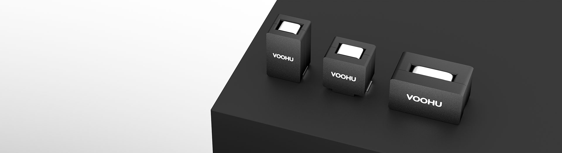
Induktivitätsprodukte
These are single-winding power bead inductors for multiphase buck converters and point-of-load stages: nanohenry inductance, sub-milliohm DC resistance and saturation currents past a hundred amps. Select on the hot saturation figure and the heating current, not the room-temperature number.
Artikelsuche und Produktauswahl
Die Tabelle verwendet die aktuellen Produktdatensätze der englischsprachigen Website, veröffentlichte Auswahlfelder und artikelspezifische Links zu technischen Dateien.
* Spalten „Bild“ und „Artikelnummer“ fixiert · horizontal ziehen, um alle Spezifikationen anzuzeigen
| Bild | Datenblatt | Vergleichen | Downloads |
Kategorie
|
Anfangsinduktivität (nH)
|
Toleranz (± %)
|
DCR (mΩ)
|
1. Sättigungsstrom bei 25 ℃ (A) (typ.)
|
2. Sättigungsstrom bei 100 ℃ (A) (typ.)
|
Erwärmungsstrom (A) (typ.)
|
Muster |
|---|
| Bild | Artikelnummer | Datenblatt | Vergleichen | Downloads | Kategorie | Anfangsinduktivität (nH) | Toleranz (± %) | DCR (mΩ) | 1. Sättigungsstrom bei 25 ℃ (A) (typ.) | 2. Sättigungsstrom bei 100 ℃ (A) (typ.) | Erwärmungsstrom (A) (typ.) | Muster |
|---|---|---|---|---|---|---|---|---|---|---|---|---|
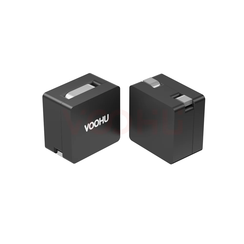 |
WHPBU-100710N-R47M0 | SPEC | WHPBU-100710N | 470 | 20 | 0.18±10% | 20 | 15 | 70 |
|
||
|
|
WHPBU-100710N-R33M0 | SPEC | WHPBU-100710N | 330 | 20 | 0.18±10% | 35 | 30 | 70 |
|
||
|
|
WHPBU-100710N-R30M0 | SPEC | WHPBU-100710N | 300 | 20 | 0.18±10% | 43 | 33 | 70 |
|
||
|
|
WHPBU-100710N-R22L0 | SPEC | WHPBU-100710N | 220 | 15 | 0.18±10% | 60 | 50 | 70 |
|
||
|
|
WHPBU-100710N-R18L0 | SPEC | WHPBU-100710N | 180 | 15 | 0.18±10% | 75 | 65 | 70 |
|
||
|
|
WHPBU-100710N-R15L0 | SPEC | WHPBU-100710N | 150 | 15 | 0.18±10% | 75 | 75 | 70 |
|
||
|
|
WHPBU-100710N-R12L0 | SPEC | WHPBU-100710N | 120 | 15 | 0.18±10% | 90 | 80 | 70 |
|
||
|
|
WHPBU-100710N-R10L0 | SPEC | WHPBU-100710N | 100 | 15 | 0.18±10% | 117 | 100 | 70 |
|
Erweitern Sie die ausgewählten Filter oder löschen Sie die aktuelle Suche.
By series
Series differ in body size, which sets DC resistance and how much current each phase carries.
So wählen Sie aus
Phase count and ripple set the inductance; thermals and peak current set the series.
Work from input and output voltage, switching frequency, phase count and the ripple you can accept. More phases and higher frequency both reduce the inductance each phase needs.
Use the saturation figure at 100 degrees, not the 25 degree number. Your per-phase peak, including load transients, has to stay inside it.
Heating current caps the continuous RMS per phase. Multiply DC resistance by that current squared to see the copper loss the board has to shed.
Check body size, land pattern and phase-to-phase spacing, then measure ripple, current sharing and temperature rise on the real board.
Parameters
Two saturation figures and a heating current, each defined under different conditions.
Measured at low current before any roll-off. Ranges from about 100 to 500 nanohenries across the WHPBU series, which suits high frequency multiphase stages.
Stated as a percentage around the initial inductance. It feeds directly into your ripple calculation, so use the worst-case corner rather than the nominal value.
Sub-milliohm across the range, from about 0.18 to 0.47 milliohm depending on series. At high phase current even a tenth of a milliohm is measurable heat.
The room-temperature limit, useful for comparing parts but optimistic for design. A real converter runs hotter than its test bench.
The figure to design against. Saturation capability falls as the core heats, so this is what your peak phase current must stay below.
The continuous RMS current that produces the datasheet's stated temperature rise. It caps steady-state load, while saturation caps the peak.
Vergleichen
DC resistance and heating current separate the series more than inductance does.
Zur Produktauswahl zurückkehren ↑| Kategorie | Artikelnummern | Anfangsinduktivität (nH) | Toleranz (± %) | DCR (mΩ) | 1. Sättigungsstrom bei 25 ℃ (A) (typ.) | 2. Sättigungsstrom bei 100 ℃ (A) (typ.) | Erwärmungsstrom (A) (typ.) | Aktion |
|---|---|---|---|---|---|---|---|---|
| WHPBU-100705N | 7 | 72, 100, 120, 150, 200, 220, 300 | 15 | 0.325±7% | 19, 30, 33, 45, 65, 70, 80 | 12, 24, 25, 35, 50, 60, 70 | 31 | Filtern → |
| WHPBU-100710N | 8 | 100, 120, 150, 180, 220, 300, 330, 470 | 15, 20 | 0.18±10% | 20, 35, 43, 60, 75, 90, 117 | 15, 30, 33, 50, 65, 75, 80, 100 | 70 | Filtern → |
| WHPBU-131308N | 6 | 110, 210, 260, 320, 440, 500 | 10, 15 | 0.32 ± 9.4% | 28, 35, 50, 60, 70, 120 | 23, 25, 35, 45, 55, 105 | 45 | Filtern → |
| WHPBU-150705N | 3 | 100, 120, 150 | 15 | 0.47±7% | 72, 87, 105 | 60, 75, 80 | 53 | Filtern → |
Anwendungsprüfung
Confirm phase count, per-phase current, switching frequency and the thermal environment.
Documents
Datasheets carry the saturation curves, heating current and recommended land pattern.
Es werden repräsentative verfügbare Dateisätze angezeigt. Suchen Sie nach einer bestimmten Artikelnummer.
Die veröffentlichten Produktinhalte von VOOHU werden vom technischen Team geprüft. Spezifikationen, Downloads und Informationen zum technischen Support sind bestimmten Artikelnummern zugeordnet, sodass Sie sie vor einer Muster- oder Angebotsanfrage prüfen können.
Kategorieübersicht
These parts are often mislabelled. Knowing what they are, and which of the three current figures to design against, prevents most of the errors.
Neues Design besprechen
FAE für eine Ersatztypenprüfung kontaktieren.
Sie haben bereits eine Artikelnummer? Muster oder Angebot anfragen.
A power bead inductor is a single winding of one or two turns over a ferrite core. It is not a coupled inductor and not a common mode choke, both of which have two windings that interact magnetically. The construction gives very low DC resistance and very high saturation current in a small body.
Saturation at 25 degrees is a comparison number. Saturation at 100 degrees is the one your peak phase current must stay under, because the core loses capability as it heats. Heating current is the continuous RMS that produces the rated temperature rise. Size the peak on the hot figure, the steady state on heating current.
With phase currents in the tens of amps, loss rises with the square of current. A part at 0.18 milliohm and one at 0.47 milliohm differ by more than a factor of two in copper loss. On a dense multiphase board that shows up directly as board temperature, so read DCR early rather than last.
FAQ
Answers cover what a power bead is, which current rating to design against and how to compare.
It is a single-winding power inductor, usually one or two turns over a ferrite core, designed for very low DC resistance and very high saturation current in a small body. It is the standard choice for multiphase buck converters powering processors, FPGAs and ASICs, where each phase carries tens of amps at low inductance.
No. A coupled inductor has two or more windings that interact magnetically and is used to shape ripple across phases. A power bead is a single winding with no magnetic coupling between phases. The two are not interchangeable, and the datasheets describe different things, so do not substitute one for the other.
The figure at 100 degrees. Saturation capability falls as the core heats, and a working converter runs well above room temperature. The 25 degree number is useful for comparing parts on equal terms, but sizing a design against it leaves no margin once the board is hot.
Heating current is the continuous RMS current that produces the temperature rise stated in the datasheet. It caps the steady-state load each phase can carry. Saturation current caps the instantaneous peak. Both have to be satisfied: heating current for the average, hot saturation for the transient.
Because loss rises with the square of current, and phase currents here are tens of amps. Across the WHPBU range DC resistance runs from about 0.18 to 0.47 milliohm, which is more than a factor of two in copper loss at the same current. On a dense board that shows up directly as temperature.
Work from input and output voltage, switching frequency, phase count and the ripple current you can accept. More phases and higher switching frequency both reduce the inductance each phase needs, which is why these parts are specified in nanohenries rather than microhenries.
It is not advisable. Phases should be as identical as possible, because differences in inductance and DC resistance cause unequal current sharing, and the phase carrying the most current runs hottest and saturates first. Use the same part across all phases and verify the sharing by measurement.
With a complete part number, send the part number, quantity, delivery region and the date you need it. If you are still selecting, send the total output current, phase count, per-phase RMS and peak current, switching frequency and ambient temperature.
Technischer Support
Senden Sie die Artikelnummer des Kandidaten und die zu prüfende Bedingung. Muster können nach Abschluss der Auswahl angefragt werden; kaufmännische Fragen lassen sich im selben technischen Austausch klären.
Dokumentrevision angeben
Temperatur, Isolationsspannung und Bezugsgrundlage für den PoE-Strom
Pinzahl, Rastermaß und Abstand zwischen den Pinreihen
Zur Priorisierung von Mustern und Evaluierung
Zeitpunkt, zu dem Sie Kandidaten und einen Vergleich der Unterschiede benötigen
Die technische Prüfung ermittelt geeignete Kandidaten und erläutert die Unterschiede.
Aus der Produktauswahl oder technischen Prüfung
Prototyp / Pilotserie / Serienfertigung
Zeitplan für Muster und Serie getrennt angeben
Konformitätsnachweise, Materialdeklarationen oder Berichte Dritter
Mustermenge, Lieferzeit und Kosten hängen von der Projektphase und der Artikelnummer ab. Der Vertrieb antwortet an Werktagen.




