IEEE 802.3bt PoE Magnetics: How to Choose the Data-Side LAN Transformer
In 4-pair operation, an IEEE 802.3bt (PoE++) port drives DC current through the cable-side center taps of the LAN transformer on all four pairs, so the data-side magnetics must carry that current and still keep the inductance the Ethernet signal needs. Check four things: the current per pair for your Type (600 mA nominal for Type 3 and 866 mA nominal for Type 4 in 4-pair operation, according to the IEEE 802.3 working group), open-circuit inductance (OCL) measured under DC bias, an operating temperature range that includes self-heating, and a separate pin for each cable-side center tap. The VOOHU WHSM24706C2 (10GBASE-T) and WHSG24Z01C0 (1000BASE-T) datasheets state a DC balance current per channel (1000 mA and 1.5 A), OCL under DC bias, −40 to +85 °C including temperature rise, and separate cable-side center-tap pins; ask our FAE team how the per-channel rating maps to your pair current.
This guide is about the signal transformer between the RJ45 connector and the PHY. It is a different part from the transformer in the powered device's isolated DC/DC converter; for that part, seePoE power transformers.
What does 802.3bt change for Ethernet magnetics?
Type 1 (802.3af) and Type 2 (802.3at) power sourcing equipment (PSE) powers two of the four pairs. IEEE 802.3bt adds Type 3 and Type 4, and according to the Ethernet Alliance overview, a PSE that assigns Class 5 or higher must power all four pairs, so all four cable-side windings carry DC.
Inside each winding, the DC splits between the two conductors of the pair. When the two halves are equal, their DC flux cancels in the core. Any difference between them leaves a net DC bias that pushes the core toward saturation and lowers its inductance, which is why the datasheet OCL test condition matters for a PoE port.
| PoE Type | Standard | PSE output power (max) | Power at the PD (max) | Pairs powered | PSE output voltage | Current per pair |
|---|---|---|---|---|---|---|
| Type 1 | IEEE 802.3af | 15.4 W | 13 W | 2 | 44–57 V | 350 mA maximum |
| Type 2 | IEEE 802.3at | 30 W | 25.5 W | 2 | 50–57 V | 600 mA maximum |
| Type 3 | IEEE 802.3bt | 60 W | 51 W | 2 or 4 (4 for Class 5 and 6) | 50–57 V | 600 mA nominal (4-pair) |
| Type 4 | IEEE 802.3bt | 90 W | 71.3 W | 2 or 4 (4 for Class 5 to 8) | 52–57 V | 866 mA nominal (4-pair) |
Sources: Ethernet Alliance, Overview of 802.3bt – Power over Ethernet standard (2019), overview figure and Tables 3, 4, 15 and 17; IEEE 802.3 Working Group liaison on P802.3bt clause referencing (May 2017) for current per pair.
802.3bt Type 3 vs Type 4: how much current does each pair carry?
The IEEE 802.3 working group calls 4-pair currents nominal (600 mA per pair for Type 3, 866 mA for Type 4) because the two pairs of the same polarity are in parallel and never share the current exactly. The Ethernet Alliance overview calls this pair-to-pair current unbalance and lists the highest current one pair can see in each class:
| PD Class | PSE output power | Highest pair current, perfect balance | Highest pair current with unbalance |
|---|---|---|---|
| Class 5 | 45 W | 450 mA | 550 mA |
| Class 6 | 60 W | 600 mA | 682 mA |
| Class 7 | 75 W | 721 mA | 784 mA |
| Class 8 | 90 W | about 0.87 A | 938 mA |
Source: Ethernet Alliance overview of 802.3bt, overview figure and Table 18. Values are per pair as listed there; check the exact definitions in IEEE 802.3 Clause 145.
For the magnetics, this means sizing the current in each winding against the unbalanced figure for your class, not against the port power divided by four. A Class 8 port can put up to 938 mA on one pair even though the nominal value is 866 mA.
Why does OCL under DC bias matter for PoE++?
OCL keeps the low-frequency content of the Ethernet signal intact, and a datasheet OCL value means little without its DC bias test condition. In the VOOHU datasheets below, that bias is far lower than the rated PoE current, and none gives OCL at full PoE current. If your design runs close to the rating, ask for OCL or insertion-loss data at your actual bias, or measure it on samples. The table in the next section lists the OCL test bias next to each PoE rating.
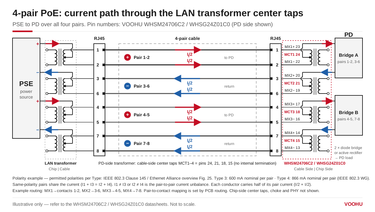
4-pair PoE current path through the cable-side center taps. Pin numbers are for the VOOHU WHSM24706C2 and WHSG24Z01C0. Illustrative only; see the datasheet.
Power enters and leaves at the cable-side center taps, so each needs its own pin: pins 24, 21, 18 and 15 on the Cable Side of the WHSM24706C2 and WHSG24Z01C0, with no termination inside the transformer. Which taps go to which supply rail is covered inPoE pinout: Mode A vs Mode B.
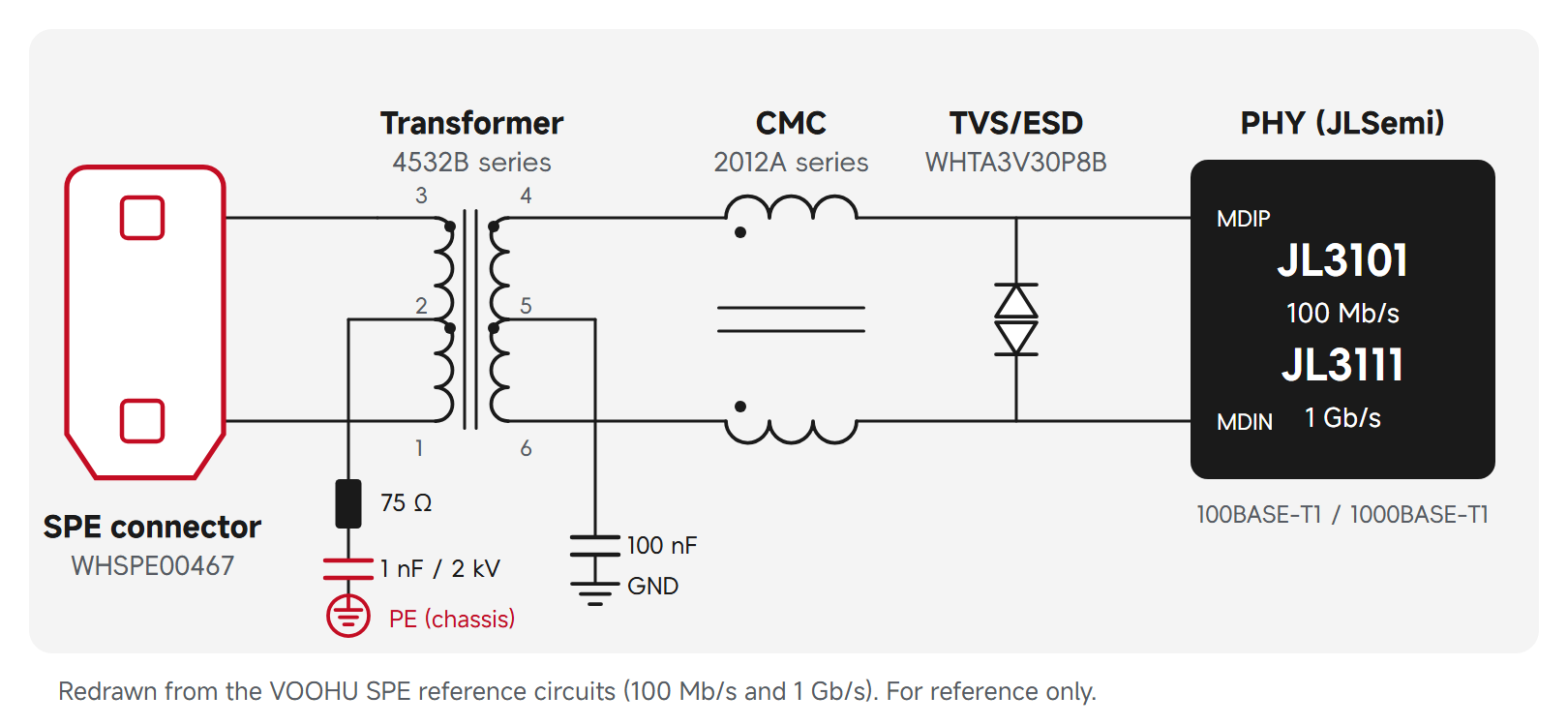
Do not tie the usual Bob Smith termination (75 Ω and 1000 pF to chassis) straight to powered center taps; TI's AN-1469 PHY layout guide notes that its Bob Smith termination does not apply to PoE. In VOOHU PoE RJ45 jacks with integrated magnetics, such as theSYT4A11Q855HWA10DPB1359, a 22 nF capacitor sits in series with each 75 Ω resistor.
Which VOOHU LAN transformers state a PoE current rating?
The datasheets below state a PoE current and OCL under DC bias, quoted in their own wording. They rate current per "channel" and for all channels or ports, not by IEEE Type or Class, soask our FAE teamhow the rating applies to your Type and pair current.
| Part number | Data rate, ports, package | PoE rating (datasheet wording) | OCL min (at DC bias) | Hi-Pot | Operating temperature |
|---|---|---|---|---|---|
| WHSM24706C2 | 10GBASE-T, single port, 24-pin SMD | PoE Support 90W; each channel 1000 mA, full channels 2000 mA DC balance current | 100 µH (18 mA) | 1500 VAC, 1 mA, 60 s | −40 to +85 °C, including temperature rise |
| WHSG24Z01C0 | 100/1000BASE-T, single port, 24-pin SMD | Each channel 1.5 A; one gigabit port (full channels) 3.0 A DC balance current | 180 µH (35 mA) | 1500 VAC, 1 mA, 60 s | −40 to +85 °C, including temperature rise |
| WHDQ96504P2 | 2.5GBASE-T / 5GBASE-T, four ports, 96 pins | PoE Support 90W; each channel 900 mA, full channels 1800 mA DC balance current | 150 µH (21 mA) | 1500 VAC, 1 mA, 60 s | 0 to +70 °C (temperature rise not stated) |
| WHSG50002P1 | 100/1000BASE-T, dual port, 50-pin SMD | "Full ports support(4PPoE)IEEE802.3bt standard----1200mA Current Capability" | 350 µH (8 mA) | 1500 VAC, 1 mA, 60 s | 0 to +70 °C, including temperature rise |
All OCL values at 100 kHz. WHSG50002P1 is tested at 8 mA, the same bias as VOOHU non-PoE gigabit parts such as WHSG24R03D0. Source: VOOHU datasheets for each part number.
Where to start:
- Single-port gigabit PSE or PD that needs the highest per-channel rating in this list:WHSG24Z01C0.
- Single-port 10GBASE-T:WHSM24706C2.
- Four-port 2.5G/5G PSE boards:WHDQ96504P2. Check heating at full load, since the datasheet does not say whether 0 to +70 °C includes temperature rise. It rates 900 mA per channel; if a channel is one pair, that is below the 938 mA Class 8 unbalance figure above, so confirm the per-channel meaning with our FAE team before using it on a Class 8 port.
- Dual-port gigabit layouts:WHSG50002P1. Ask our FAE team which Type and pair current its 1200 mA figure covers.
For more parts and PoE current ratings, filter theLAN transformer selectorby its PoE column. For multi-port PSE layout, see thePoE switch PSE port design guide.
Discrete LAN transformer or RJ45 with integrated magnetics for 802.3bt?
An RJ45 jack with integrated magnetics saves board area, but its current rating, standard statement and OCL bias vary from part to part and must be read from its own datasheet. A discrete LAN transformer next to a plain RJ45 connector offers a wider choice of current ratings. A plain RJ45 connector has no PoE rating of its own; check its contact current rating. SeePoE integrated magnetic RJ45 selectionandPoE Ethernet port design: six common questions.
FAQ
Q1: Is 802.3bt the same as PoE+?
No. PoE+ usually means IEEE 802.3at (Type 2, up to 30 W at the PSE). IEEE 802.3bt, often called PoE++ or 4-pair PoE, adds Type 3 (up to 60 W at the PSE) and Type 4 (up to 90 W at the PSE).
Q2: What is the difference between 802.3bt Type 3 and Type 4?
Type 3 goes up to Class 6 (60 W at the PSE, 51 W at the PD); Type 4 must support Class 7 and may support Class 8 (up to 90 W at the PSE, 71.3 W at the PD), always over four pairs at those classes. The nominal current per pair rises from 600 mA to 866 mA.
Q3: How much power can 802.3bt (PoE++) deliver to devices?
Up to 71.3 W at a Class 8 PD (90 W at the PSE); 51 W at a Class 6 PD on a Type 3 PSE.
Q4: What are magnetics in Ethernet?
"Magnetics" means the LAN transformer and common mode choke between the PHY and the RJ45 connector. They pass the data signal and isolate the device from the cable; in PoE equipment, the transformer's cable-side center taps also carry the DC power.
Q5: Can I use a non-PoE LAN transformer in a PoE++ port?
Not without supporting data. A part whose datasheet gives no PoE current and tests OCL at a low bias, such as 8 mA on the VOOHU WHSG24R03D0, is not specified for 802.3bt current. Choose one that states a PoE current and OCL under DC bias.
Get your 802.3bt magnetics checked
Send your PoE Type and Class, PSE or PD side, data rate and port count through thesample and support request form. Our FAE team can suggest LAN transformers for your pair current and confirm how the per-channel rating applies. Samples are available for evaluation, and selected parts are free of charge. Our FAE team will be glad to confirm the options for your project.
VOOHU supplies RJ45 and SFP connectors, LAN and PoE transformers and common mode chokes from Suzhou, China, to more than 1,500 customers.
 WHSG50002P1 1000 BASE-T Dual Ports 50 PIN 4PPoE (up to 1200 mA) LAN Transformer
> View Details
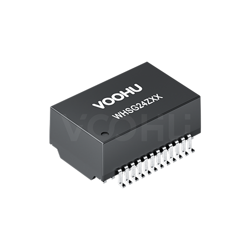 WHSG24Z01C0 100/1000Base-T Single Ports 24PIN 4PPOE(up to 3000mA) LAN Transformer
> View Details
 WHDQ96504P2 Quad Ports 2.5G/5G DIP 96PIN LAN Transformer
> View Details
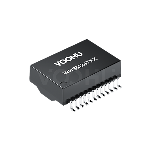 WHSM24706C2 10G Base-T Single Port 24PIN PoE++ LAN Transformer
> View Details