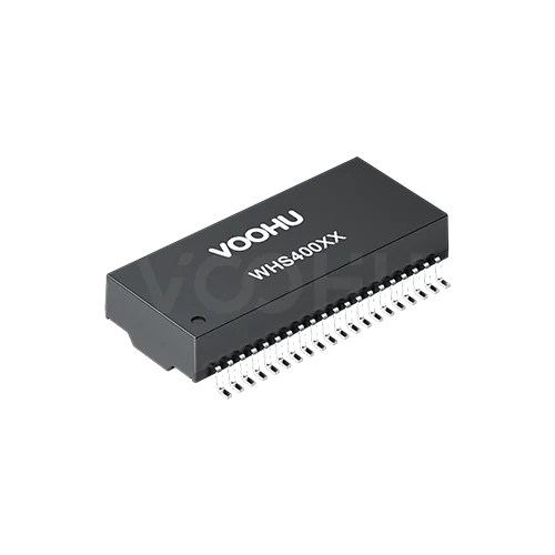
Mentech H4001CG Alternative: VOOHU WHS40005G Comparison
VOOHU WHS40005G is a functional alternative to the Mentech H4001CG — verify with samples in your design. Both are 10/100 quad-port LAN transformers in a 40-pin, 1.27 mm pitch surface-mount package, with 24.13 mm from the first to the last lead of a row, 1CT:1CT windings, 350 µH minimum OCL at 8 mA DC bias, 1500 V isolation and a 0 to +70 °C operating range, and both datasheets put the centre taps on the same pins. Two items need a check before you reuse a layout. On four channels the datasheets print the + and − labels the opposite way round, although the polarity dots give the same in-phase pin pairs. And the suggested pads span 17.2 mm, outer edge to outer edge, on the Mentech datasheet against 17.00 mm on the VOOHU datasheet.
产品WHS40005G
What the H4001CG and WHS40005G datasheets print, parameter by parameter
The Mentech figures come from the one-page H4001CG datasheet carried on distributor listings; it shows no revision number or date. The VOOHU figures come from the WHS40005G datasheet, revision A0, which has the mechanical drawing, suggested pad layout and schematic on page 1 and the electrical limits on page 2. Lengths are in millimetres, and a tolerance appears only where the drawing prints one. Pin names and the position of each polarity dot follow in a separate table below.
| Parameter | Mentech H4001CG (source) | VOOHU WHS40005G (source) |
|---|---|---|
| Data rate / ports | 10/100 Base-T, quad port; IEEE 802.3u (DS) | 10/100BASE-TX (DS p1 title); four ports, each with a TD and an RD channel (DS p1 schematic) |
| Package | Surface mount, open header, 40 pins (DS) | SMD, 40 pins (DS p1) |
| Body length × width | 28.1 × 12.1; untoleranced dimensions ± 0.25 (DS) | 28.00 ± 0.50 × 12.00 ± 0.50 (DS p1) |
| Width across leads | 16.0 (DS) | 16.00 ± 0.50 (DS p1) |
| Height, from seating plane | 6.4 max (DS) | 5.70 ± 0.50 (DS p1) |
| Lead pitch / lead width | 1.27 / 0.46 (DS) | 1.27 ± 0.20 / 0.46 ± 0.10 (DS p1) |
| First to last lead, centre to centre | 24.13 (DS) | 24.13 ± 0.20 (DS p1) |
| Standoff | 0.3 ± 0.15 (DS) | 0.25 ± 0.15 (DS p1 side view) |
| Lead thickness / foot length | Not stated | 0.25 ± 0.10 / 1.25 ± 0.15 (DS p1) |
| Coplanarity | 0.10 (DS) | 0.1 (DS p1) |
| Suggested pads: width / length / pitch | 0.76 / 2.54 / 1.27 (DS) | 0.76 typ / 2.54 typ / 1.27 typ (DS p1) |
| Suggested pads: outer edge to outer edge across both rows | 17.2 (DS) | 17.00 typ (DS p1) |
| Centre taps, chip side | TCT on 3, 8, 13, 18 (DS) | CT4 3, CT3 8, CT2 13, CT1 18 (DS p1) |
| Centre taps, cable side | MCT on 38, 33, 28, 23 (DS) | CMGND on 38, 33, 28, 23 (DS p1) |
| Each channel, as drawn | Transformer, then a common mode choke on the cable side; two channels share one chip-side and one cable-side centre tap (DS) | Transformer, then a common mode choke on the cable side; two channels share one chip-side and one cable-side centre tap (DS p1) |
| Turns ratio | 1CT:1CT ± 2% (DS) | 1CT:1CT ± 5% (DS p2) |
| OCL | 350 µH min, 100 kHz, 0.2 V, 8 mA DC bias (DS) | 350 µH min, 100 kHz, 0.1 V, 8 mA DC bias (DS p2) |
| Leakage inductance / DCR | Not stated | 0.5 µH max at 100 kHz, 0.1 V / 1400 mΩ max (DS p2) |
| Insertion loss | −1.1 dB max, 0.5–100 MHz (DS) | −1.1 dB max, 1–100 MHz (DS p2) |
| Return loss | −18 dB min, 0.5–30 MHz; −12 + 20log(f/80) dB, 30.1–60 MHz; −12 dB, 60.1–80 MHz (DS) | −18 dB min, 1–30 MHz; −14.4 dB at 40 MHz; −13.1 dB at 50 MHz; −12 dB, 60–80 MHz (DS p2) |
| Crosstalk | −35 dB min, 0.5–40 MHz; −33 + 20log(f/50) dB, 40.1–100 MHz (DS) | −30 dB min, 1–100 MHz (DS p2) |
| Common mode rejection | −30 dB min, 0.5–100 MHz (DS) | −30 dB min, 1–100 MHz (DS p2) |
| Isolation (hipot) | 1500 Vrms; test time not stated (DS) | 1500 VAC, 1 mA, 60 s (DS p2) |
| Operating temperature | 0 to +70 °C (DS) | 0 to +70 °C (DS p2) |
Ethernet transformer polarity: why four channels carry opposite +/− labels
| Chip-side pins | Mentech label | VOOHU label | Cable-side pins | Mentech label | VOOHU label | Dotted pins (Mentech / VOOHU) |
|---|---|---|---|---|---|---|
| 1, 2 | TD1+, TD1− | TD4+, TD4− | 40, 39 | MX1+, MX1− | TX4+, TX4− | 1, 40 / 1, 40 |
| 3 | TCT | CT4 | 38 | MCT | CMGND | — |
| 4, 5 | TD2+, TD2− | RD4+, RD4− | 37, 36 | MX2+, MX2− | RX4+, RX4− | 4, 37 / 4, 37 |
| 6, 7 | TD3+, TD3− | RD3−, RD3+ | 35, 34 | MX3+, MX3− | RX3−, RX3+ | 6, 35 / 7, 34 |
| 8 | TCT | CT3 | 33 | MCT | CMGND | — |
| 9, 10 | TD4+, TD4− | TD3−, TD3+ | 32, 31 | MX4+, MX4− | TX3−, TX3+ | 9, 32 / 10, 31 |
| 11, 12 | TD5+, TD5− | TD2+, TD2− | 30, 29 | MX5+, MX5− | TX2+, TX2− | 11, 30 / 11, 30 |
| 13 | TCT | CT2 | 28 | MCT | CMGND | — |
| 14, 15 | TD6+, TD6− | RD2+, RD2− | 27, 26 | MX6+, MX6− | RX2+, RX2− | 14, 27 / 14, 27 |
| 16, 17 | TD7+, TD7− | RD1−, RD1+ | 25, 24 | MX7+, MX7− | RX1−, RX1+ | 16, 25 / 17, 24 |
| 18 | TCT | CT1 | 23 | MCT | CMGND | — |
| 19, 20 | TD8+, TD8− | TD1−, TD1+ | 22, 21 | MX8+, MX8− | TX1−, TX1+ | 19, 22 / 20, 21 |
Pin names and dot positions as printed on the H4001CG datasheet schematic and on page 1 of the WHS40005G datasheet.
In a transformer symbol, the dot marks the winding ends that swing positive together. For the channel on pins 6/7 and 35/34, Mentech puts the dots on pins 6 and 35 and labels those pins +; VOOHU puts the dots on pins 7 and 34 and labels those pins +. Either way, pin 6 is in phase with pin 35 and pin 7 with pin 34, because the dotted ends pair with each other and so do the undotted ends. The same holds for 9/32 and 10/31, 16/25 and 17/24, and 19/22 and 20/21. Read like this, a board routed to the Mentech net names still passes each pair through the transformer with the same end-to-end polarity; only the +/− text differs. That conclusion comes from reading the two published schematics, not from a written FAE confirmation, so check each of these pins against both schematics and verify the link on a sample build.
The channel names also run in a different order. Mentech numbers its eight chip-side windings TD1 to TD8 and the cable-side windings MX1 to MX8, starting at pin 1. VOOHU names four ports from 4 down to 1, each with a TD/TX and an RD/RX channel, so port 4 sits on pins 1 to 5 and 36 to 40. If you import the VOOHU schematic symbol into your library, map the nets by pin number rather than by label, then compare the netlist with your existing H4001CG design.
Land pattern, height and limits on a 40-pin quad-port footprint
Pad span: 17.2 mm against 17.00 mm. Both suggested layouts use 0.76 × 2.54 mm pads on a 1.27 mm pitch, and both measure the overall span from the outer edge of one pad row to the outer edge of the other: 17.2 mm on the Mentech datasheet, 17.00 mm on the VOOHU datasheet, a difference of 0.20 mm across the two rows. The 24.13 mm first-to-last lead distance and the 16.0 mm width across the leads carry the same values on both. Lay the VOOHU pattern over your H4001CG pads in CAD, then inspect the heel and toe fillets on a sample build before deciding whether the existing pads stay.
Height, standoff and body. The H4001CG is 6.4 mm maximum from the seating plane; the WHS40005G is 5.70 ± 0.50 mm, so its 6.20 mm upper limit stays under the Mentech maximum. Size any lid or board clearance from 6.20 mm rather than 5.70 mm. Standoff, between the seating plane and the underside of the body, is 0.3 ± 0.15 mm against 0.25 ± 0.15 mm. The body is 28.1 × 12.1 mm on the Mentech drawing and 28.00 ± 0.50 × 12.00 ± 0.50 mm on the VOOHU drawing, and coplanarity is 0.10 mm on both. Take the courtyard, silkscreen outline and placement-machine body data from the VOOHU drawing.
Turns-ratio tolerance and test conditions. Both datasheets give 1CT:1CT, with a ± 2% tolerance on the Mentech sheet and ± 5% on the VOOHU sheet. OCL is 350 µH minimum at 100 kHz and 8 mA DC bias on both, with a 0.2 V test signal for Mentech and 0.1 V for VOOHU. Insertion loss (−1.1 dB maximum) and common mode rejection (−30 dB minimum) share their numbers, over bands that start at 0.5 MHz for Mentech and 1 MHz for VOOHU; return loss and crosstalk use different band splits and formulas, so read them from the table rather than as one figure. Isolation is 1500 Vrms with no stated test time on the Mentech sheet and 1500 VAC at 1 mA for 60 s on the VOOHU sheet. Where a quality plan quotes any of these limits, align it with the datasheet of the part you approve.
Which multi-port 10/100 designs suit the WHS40005G?
The WHS40005G puts four 10/100BASE-TX ports in one 40-pin package, typically between a quad-port PHY or a switch IC with integrated PHYs and four RJ45 jacks: small four-port switches, multi-port industrial gateways and embedded controllers that need several Ethernet ports, running within 0 to +70 °C. Where the ports must operate from −40 to +85 °C, the WHS40005TG product page lists that range; compare its own datasheet and drawing with your board before using it. For gigabit designs with four ports, see our quad-port gigabit LAN transformer selection guide.
FAQ
Q1: What is an alternative to Mentech H4001CG?
VOOHU offers the WHS40005G as a functional alternative to the Mentech H4001CG — verify with samples in your design. Both are quad-port 10/100 LAN transformers in 40-pin SMD packages on 1.27 mm pitch, with 1CT:1CT windings, 350 µH minimum OCL, 1500 V isolation and a 0 to +70 °C rating. Check the +/− labels on four channels against both schematics, and the suggested pad span of 17.2 mm on the Mentech datasheet against 17.00 mm on the VOOHU datasheet.
Q2: How do the H4001CG and WHS40005G pinouts compare?
On both datasheets the centre taps are on pins 3, 8, 13 and 18 (chip side) and 38, 33, 28 and 23 (cable side), and each signal pair uses the same two pin numbers. The names differ: Mentech labels its channels TD1–TD8 and MX1–MX8 from pin 1, while VOOHU names four ports, 4 down to 1, with TD/RD and TX/RX. On pins 6/7, 9/10, 16/17 and 19/20 and their cable-side partners the + and − labels are reversed, yet the polarity dots give the same in-phase pin pairs. Check your netlist by pin number against both schematics.
Q3: What does the dot mean on an Ethernet transformer schematic?
The dot marks the end of each winding with the same instantaneous polarity: when the dotted end of the chip-side winding goes positive, the dotted end of the cable-side winding goes positive too. On the H4001CG schematic the dots for one channel sit on pins 6 and 35; on the WHS40005G schematic they sit on pins 7 and 34. Both describe pin 6 in phase with pin 35 and pin 7 with pin 34, which is why the different +/− labels do not change which pins pair up.
Q4: Do I need a new footprint to evaluate the WHS40005G on an H4001CG board?
That depends on your land pattern. Pad size (0.76 × 2.54 mm), pitch (1.27 mm) and the first-to-last lead distance (24.13 mm) carry the same values; the outer pad span is 17.2 mm on the Mentech datasheet and 17.00 mm on the VOOHU datasheet. That comparison comes from two public datasheets, not a written FAE confirmation, so send your layout to our FAE team and solder a sample before release.
Send your H4001CG schematic and land pattern with a WHS40005G sample request
Add the schematic page that carries the H4001CG, and your land pattern, to a sample request for the WHS40005G. Samples are available for evaluation, and selected parts are free of charge. Our FAE team will be glad to confirm the options for your project. Our FAE team can suggest suitable parts and help check the design — for this pair, the pin-by-pin mapping on the four channels with reversed +/− labels, the 17.2 / 17.00 mm pad span and the clearance above the 6.20 mm upper height limit.
VOOHU supplies RJ45 and SFP connectors, LAN and PoE transformers and common mode chokes from Suzhou, China, to more than 1,500 customers.
To see the other 40-pin quad-port parts for 10/100 ports, open the LAN transformer selector, already filtered to 10/100 Base-TX, quad ports and 40 pins, and narrow it by mounting or temperature.
Related products: WHS40005G — quad-port 10/100BASE-TX SMD LAN transformer, 40 pins on 1.27 mm pitch, 28.00 × 12.00 mm body, 5.70 ± 0.50 mm high, 1CT:1CT, 350 µH minimum OCL, 1500 VAC isolation, 0 to +70 °C. WHS40005TG — quad-port 10/100BASE-TX SMD LAN transformer, 40 pins, listed for −40 to +85 °C.
方案/solution-ethernet/