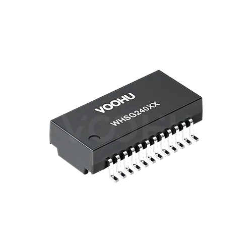
Pulse HX5084NLT Alternative: VOOHU WHSG24002TG Comparison
The Pulse HX5084NLT is the tape-and-reel version of the HX5084NL, a single-port gigabit LAN transformer in a 24-lead SMD package on a 0.039 in (about 1.0 mm) pitch. The VOOHU WHSG24002TG is a functional alternative to it — verify with samples in your design. The two datasheets list the same pin names on the same 24 pins, 350 µH minimum OCL with 8 mA DC bias, 1500 V isolation for 60 s, and a −40 to +85 °C operating range. The main difference is inside: the Pulse schematic shows one 1:1 transformer per channel and no common mode choke, while the VOOHU schematic adds a two-wire common mode choke on the cable side of each channel. The suggested land patterns also differ in pad length and inner spacing, so plan an EMC comparison and a pad overlay as part of the evaluation.
[Product] WHSG24002TG
HX5084NL vs. WHSG24002TG: datasheet comparison
Pulse publishes one three-page datasheet for the HX5084NL, revision A, and note 5 on sheet 1 identifies the T suffix as the tape-and-reel package, so the HX5084NLT datasheet is that same document. Sheet 1 holds the notes, sheet 2 the schematic and electrical table, sheet 3 the outline and suggested pads. Its drawings are in inches, with millimetres marked for reference only; the table keeps the inch value first. The VOOHU WHSG24002TG datasheet, revision A0, is metric: page 1 carries the outline, suggested pads and schematic, page 2 the electrical items C.1 to C.11. Values marked derived are calculated from printed spans.
| Parameter | Pulse HX5084NL / HX5084NLT (datasheet rev. A) | VOOHU WHSG24002TG (datasheet rev. A0) |
|---|---|---|
| Ports / standard | Single port, four channels; "MEETS IEEE 802.3" (sheet 2) | 100/1000BASE-T, single port (p1) |
| Each channel | One 1:1 transformer (T1–T4) with center taps on both sides; no common mode choke drawn (sheet 2) | 1CT:1CT transformer followed by a two-wire common mode choke on the cable side; MCT from the transformer's cable-side center tap (p1) |
| Pin names | PCB side 1–12: TCT1, TD1+, TD1− through TCT4, TD4+, TD4−; cable side 24–13: MCT1, MX1+, MX1− through MCT4, MX4+, MX4− (sheet 2) | Same names on the same pins (p1) |
| Leads / pitch | 24; .039 in (sheet 3) | 24; 1.00 ± 0.20 mm (p1) |
| First to last lead | 11 × .039 = .429 in (sheet 3) | 11.00 ± 0.20 mm (p1) |
| Body length | .600 in max (15.24 mm) (sheet 3) | 15.10 ± 0.50 mm (p1) |
| Body width | .300 in (7.62 mm), ± .01 in (sheet 3) | 7.10 ± 0.50 mm (p1) |
| Width across leads | .405 in max (10.29 mm) (sheet 3) | 10.00 ± 0.50 mm (p1) |
| Height | .163 in max (4.14 mm) (sheet 3) | 4.00 ± 0.50 mm (p1) |
| Lead width / foot length | .015 in (0.38 mm) / .035 in (0.89 mm) (sheet 3) | 0.40 ± 0.10 / 0.90 ± 0.15 mm (p1) |
| Suggested pad width | .025 in (0.64 mm) (sheet 3) | 0.60 mm typ (p1) |
| Suggested pad length | About .070 in (1.78 mm), derived (sheet 3) | 1.35 mm typ (p1) |
| Suggested pads, inner edge to inner edge | .284 in (7.21 mm) (sheet 3) | About 8.00 mm, derived (p1) |
| Suggested pads, outer edge to outer edge | .424 in (10.77 mm) (sheet 3) | 10.70 mm typ (p1) |
| OCL | 350 µH min at 100 kHz, 100 mVrms, 8 mA DC bias, −40 to 85 °C (sheet 2) | 350 µH min at 100 kHz, 0.1 V, 8 mA DC bias (p2, C.1) |
| Turns ratio | 1 : 1 ± 2% (sheet 2) | 1CT:1CT ± 5% (p2, C.4) |
| Leakage inductance / DCR | Not stated | 0.5 µH max / 1400 mΩ max (p2, C.2, C.3) |
| Insertion loss | −1.2 dB max at 100 kHz; −0.2 − 0.002·f^1.4 dB max, 1–125 MHz (sheet 2) | −1.1 dB max, 1–100 MHz (p2, C.5) |
| Return loss | −16 dB min, 0.1–40 MHz; −10 + 20log(f/80) dB min, 40–100 MHz (sheet 2) | −18 dB, 1–30 MHz; −14.4 dB at 40 MHz; −13.1 dB at 50 MHz; −12 dB, 60–80 MHz; −10 dB at 100 MHz (p2, C.6) |
| Crosstalk | −50 dB min at 1 MHz; −55 + 22log(f/10) dB, 10–100 MHz (sheet 2) | −30 dB min, 1–100 MHz (p2, C.7) |
| Common mode rejection | −50 dB min at 2 MHz; −15 + 20log(f/200) dB, 30–200 MHz (sheet 2) | −30 dB min, 1–100 MHz (p2, C.8) |
| Isolation (hipot) | 1500 Vrms min, 60 s (sheet 2) | 1500 VAC, 1 mA, 60 s (p2, C.9) |
| Operating temperature | −40 to +85 °C (sheet 2) | −40 to +85 °C (p2, C.10) |
| Storage temperature | −50 to +125 °C (sheet 1, note 3) | −40 to +85 °C (p2, C.11) |
| Moisture sensitivity / soldering | J-STD-020 MSL 1; J-STD-075 R7, 245 °C max (sheet 1, note 4) | Not stated |
| Case material | DAP, UL 94V-0 (sheet 1, note 2) | Not stated |
| Packaging | T suffix: tape and reel (sheet 1, note 5) | 800 pcs per 330 mm reel (p2) |
| PoE rating | Not stated (sheet 2) | Not stated in the datasheet; product page: not PoE rated |
Ethernet transformer with or without a common mode choke: what the change means for your board
On sheet 2 of the Pulse datasheet, each of the four channels is a single 1:1 transformer, T1 to T4, with a center tap on the PCB side (TCT) and one on the cable side (MCT), and nothing else drawn between the PHY pins and the cable pins. On page 1 of the VOOHU datasheet, each channel has a 1CT:1CT transformer, and its cable-side data lines then run through a two-wire common mode choke before they reach the MX pins; MCT still comes from the transformer's own cable-side center tap. The pin names do not change, so the netlist stays the same. What changes is the impedance that common-mode noise meets between the transformer and the RJ45, and neither datasheet tells you which way that moves your emissions or immunity results.
Three checks follow. First, look at what the original design did about the missing choke. If the board carries a separate common mode choke between the HX5084NL and the RJ45, or a filter that was tuned during EMC work, the WHSG24002TG adds a second choke in the same path; decide whether the discrete part stays, and test both ways if you are unsure. Second, read your PHY vendor's reference design and layout guide for the magnetics arrangement they specify, and compare it with the VOOHU page 1 schematic before you sign off. Third, run the comparison on hardware: conducted and radiated pre-scans with the same cable, link partner, traffic and chassis setup that the Pulse build passed with, plus a link-error log under load, so any change in the data path shows up next to the emissions result. Our guide to Ethernet port test failures covers the termination network around the magnetics.
HX5084NL footprint on a 1.0 mm pitch: same rows, different pads
Pulse dimensions the HX5084NL in inches: a .039 in pitch with 11 × .039 = .429 in from the first lead to the last. VOOHU prints 1.00 ± 0.20 mm and 11.00 ± 0.20 mm. The drawings use different units and neither states an exact conversion for these spans, so overlay the two patterns at full scale rather than assume the rows line up lead for lead. Across the rows, the outer edges almost coincide, .424 in (10.77 mm) for Pulse against 10.70 mm for VOOHU. The inner edges do not: Pulse puts them .284 in (7.21 mm) apart, while VOOHU's 1.35 mm pads leave about 8.00 mm (derived). So a board built to the Pulse pattern has pads about 1.78 mm long (derived) that reach roughly 0.4 mm further in on each side (derived), and they are 0.64 mm wide against VOOHU's 0.60 mm. Place the WHSG24002TG leads, 10.00 ± 0.50 mm across with a 0.90 ± 0.15 mm foot, on those pads at both tolerance limits, and let the first article show heel fillets, solder volume on the longer pads, and any bridging at the 1.0 mm pitch. No written FAE confirmation covers the Pulse pads, so treat that board as a trial build.
Maximum values against nominal ± tolerance: keep-out and clearance
The two outlines are written in different ways, and that matters more than the nominal numbers. Pulse gives ceilings: .600 in (15.24 mm) long, .405 in (10.29 mm) across the leads and .163 in (4.14 mm) tall, all maximum. VOOHU gives nominal values with ± 0.50 mm: 15.10, 10.00 and 4.00 mm, which allow up to 15.60, 10.50 and 4.50 mm. If your courtyard, a shield can or the enclosure above the transformer was sized from the Pulse maximums, recheck it against the VOOHU upper limits; length and height each sit 0.36 mm above the Pulse maximums and the width across the leads 0.21 mm (derived). Measure a few samples as well, but size the design from the datasheet limits rather than from the parts you happen to receive.
For component engineers and incoming inspection, three entries change. The turns ratio tolerance is ± 2% on the Pulse sheet and ± 5% on the VOOHU sheet, so the acceptance limit on your inspection sheet should follow the part you receive. Storage temperature is −50 to +125 °C for Pulse and −40 to +85 °C for VOOHU; update the storage condition in your stores system. And only Pulse states a moisture sensitivity level and reflow limit, MSL 1 under J-STD-020 and 245 °C maximum under J-STD-075; do not carry those over to the WHSG24002TG by assumption, ask us for its data in writing before the first reel goes to the line. The insertion loss, return loss, crosstalk and common mode rejection limits are written over different frequency bands and formulas, so read them band by band rather than column against column.
Who checks what before the WHSG24002TG replaces an HX5084NLT
| Who | Check | Done when |
|---|---|---|
| Hardware | Any discrete common mode choke or tuned filter between the transformer and the RJ45 identified; decision recorded to keep or remove it | Schematic updated, or both options queued for EMC |
| Hardware | PHY reference design and layout guide read for the magnetics arrangement; library symbol shows the cable-side two-wire choke | Symbol matches the WHSG24002TG page 1 drawing |
| EMC / design verification | Conducted and radiated pre-scans with the same cable, link partner, traffic and chassis as the Pulse build; link errors logged under load | Results compared side by side and accepted |
| Layout | Inch-dimensioned Pulse pads (.284 in / .424 in, .025 in wide) and the WHSG24002TG leads overlaid at full scale, both tolerance limits | Pad set decided: keep for the trial, or move to 10.70 mm outer, 1.35 × 0.60 mm pads |
| Mechanical | Courtyard, shield and enclosure clearance checked against 15.60 × 10.50 mm and 4.50 mm | Drawings checked |
| SMT / EMS | First article: heel fillets, solder volume, bridging at 1.0 mm pitch; stencil aperture reviewed | First article signed off |
| Quality / stores | Turns ratio limit ± 5%; storage −40 to +85 °C; MSL and reflow data received from VOOHU in writing | Inspection sheet and moisture-control entry written to the WHSG24002TG datasheet |
Where the WHSG24002TG fits
The WHSG24002TG suits a single gigabit Ethernet port on a board laid out for a narrow 24-lead transformer on a 1.0 mm pitch, operating within −40 to +85 °C, where the design team is willing to verify the added cable-side choke against its EMC results. If you are working through other Pulse transformers in the same product, our HX5120NL evaluation covers another pair; for a Mentech part in a 1.0 mm-pitch package, see the G2401CG comparison.
[Solution] /solution-ethernet/
FAQ
Q1: What is an equivalent for Pulse HX5084NLT?
The VOOHU WHSG24002TG is a functional alternative to the Pulse HX5084NLT — verify with samples in your design. Both are single-port gigabit LAN transformers in a 24-lead SMD package on a pitch of about 1.0 mm, with the same pin names, 350 µH minimum OCL at 8 mA DC bias, 1500 V isolation for 60 s and a −40 to +85 °C operating range. The WHSG24002TG adds a cable-side common mode choke and uses a different suggested pad geometry.
Q2: What is the difference between HX5084NL and HX5084NLT?
Note 5 on sheet 1 of the Pulse datasheet identifies the T suffix as the tape-and-reel package. The HX5084NL and HX5084NLT therefore share one datasheet, and the comparison values in this article apply to both.
Q3: Does the HX5084NLT have a common mode choke?
The schematic on sheet 2 of the Pulse datasheet shows one 1:1 transformer per channel and no common mode choke. The VOOHU WHSG24002TG schematic shows a 1CT:1CT transformer with a two-wire common mode choke on the cable side of each channel. When you move between the two, check the magnetics against your PHY reference design and compare EMC pre-scan results.
Q4: What does the HX5084NLT datasheet say about MSL and reflow?
Note 4 on sheet 1 gives moisture sensitivity level 1 under J-STD-020 and a 245 °C maximum under J-STD-075 R7. The WHSG24002TG datasheet does not state an MSL or reflow limit, so request both from VOOHU in writing before you set the part up in your moisture-control system.
Get WHSG24002TG samples for a trial build
When you request WHSG24002TG samples, send the port schematic from the PHY to the RJ45, including any choke or filter already on the board, and the land pattern from your HX5084NLT layout. Samples are available for evaluation, and selected parts are free of charge. Our FAE team will be glad to confirm the options for your project. Our FAE team can suggest suitable parts and help check the design — for this pair, the cable-side choke against your PHY reference design and any discrete choke you already have, and how the WHSG24002TG leads sit on the inch-dimensioned Pulse pads.
VOOHU supplies RJ45 and SFP connectors, LAN and PoE transformers and common mode chokes from Suzhou, China, to more than 1,500 customers.
The LAN transformer selector opens with the gigabit, 24-pin and 1.0 mm pitch filters set, if you want to compare the parts in this package side by side.
Related product: WHSG24002TG, a single-port 100/1000BASE-T SMD LAN transformer: 24 leads at 1.00 mm, 15.10 × 7.10 × 4.00 mm nominal body (± 0.50 mm), OCL of at least 350 µH at 8 mA DC bias, a two-wire common mode choke on the cable side of each channel, isolation tested at 1500 VAC for 60 s, operating range −40 to +85 °C.