Push-Pull vs Flyback Converter: Which Isolated Topology Should You Choose?
Choose a push-pull converter when the input is a fixed low-voltage rail and you need a simple isolated bias supply, for example for an isolated RS-485, CAN or SPI interface. A driver such as TI's SN6501 switches a center-tapped transformer from a 3.3 V or 5 V supply at a fixed 50% duty cycle, and the output follows the turns ratio. Choose a flyback converter when the input varies over a wide range, when a controller has to regulate the output, or when one transformer must supply several outputs: the flyback transformer stores energy while the switch is on and delivers it when the switch turns off. The magnetics differ too. A push-pull transformer needs a center-tapped primary with balanced volt-seconds; a flyback transformer is designed to store energy. VOOHU supplies both push-pull transformers and flyback and PoE power transformers.
Flyback vs push-pull converter: what is the difference?
In a push-pull converter, two ground-referenced switches take turns driving the two halves of a center-tapped primary. Energy reaches the output while each switch conducts, and the core flux is pushed one way in one half-cycle and pulled back in the next, so the core is driven in both directions. The TI SN6501 datasheet notes that the open end of the primary rises to twice the input voltage, and that a short break-before-make time keeps both ends of the primary from being shorted. For a step-by-step walk-through, see how a push-pull converter works.
In a flyback converter, a single main switch connects the primary across the input. According to TI's seminar paper Under the Hood of Flyback SMPS Designs (SLUP254), while the switch is on the secondary diode blocks and energy is stored in the transformer; when it turns off, the leakage energy is absorbed by a clamp circuit and the stored energy flows to the output through the diode, so input and output current are pulsating. The core is magnetized in one direction only, which is why a flyback transformer is built to store energy rather than only to pass it through.
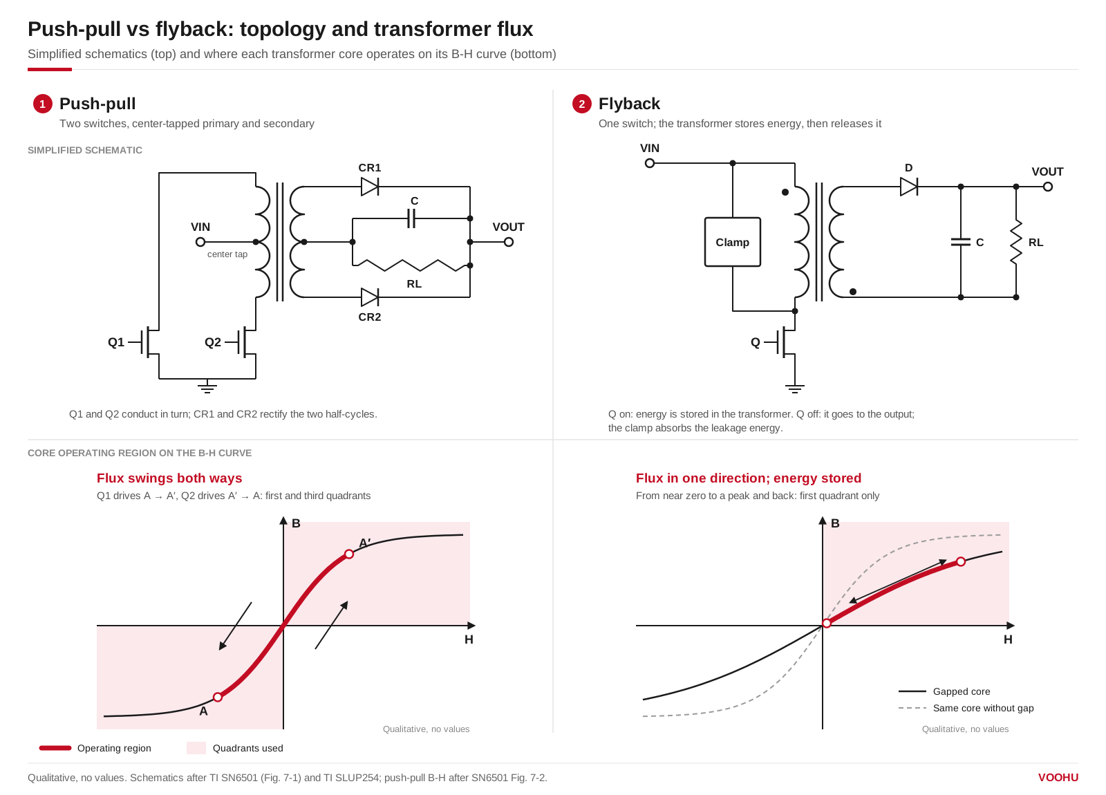
Simplified push-pull and flyback converters and where each transformer operates on its B-H curve: both directions for push-pull, one direction with stored energy for flyback. Qualitative, no values.
Isolated DC-DC converter topology: which one fits your design?
| Your design | Push-pull | Flyback |
|---|---|---|
| Input voltage | A fixed rail; the SN6501 runs from 3.3 V or 5 V | A wide-range input, such as a 48 V bus or a PoE input |
| Output regulation | Fixed 50% duty cycle, output set by the turns ratio; TI's design example adds an LDO | Regulated by the controller in a closed loop |
| Switches | Two, both ground-referenced; the open end of the primary reaches 2 × the input | One main switch, plus a clamp for the leakage energy |
| Current waveforms | Low ripple on the rectified output | Pulsating input and output current |
| Transformer | Center-tapped primary; both half-cycles must have equal volt-seconds | Stores energy every cycle; primary inductance and leakage inductance are key datasheet lines |
| Typical uses | Isolated CAN, RS-485, RS-422, RS-232, SPI, I²C and low-power LAN supplies | Wide-input and multiple-output supplies, including PoE powered devices; multiple-output flyback is popular for its simplicity and low cost |
Push-pull entries follow the TI SN6501 datasheet; the flyback entries on current waveforms, the clamp and multiple outputs follow TI SLUP254. For forward, half-bridge and full-bridge options, see the five-topology comparison in our push-pull converter article.
What are the downsides of using a flyback converter?
Most of them come from the energy the transformer has to store and release. SLUP254 lists the points to plan for: input and output current are pulsating; clamp circuits and snubbers are needed for the primary switch and the secondary rectifiers; and in a multiple-output design the windings cannot all be equally well coupled to the core gap, which often results in poor cross-regulation. Leakage inductance depends on winding geometry, the number of turns and the spacing between primary and secondary, and a high-permeability core does not lower it. So it is a transformer specification to check on the datasheet, not a fixed property of the topology.
Push-pull converter advantages and disadvantages
The advantages are a simple drive and a quiet output. Both switches are referenced to ground, and the SN6501 datasheet notes low ripple on the rectified output, which permits small output capacitors. The drawbacks: the primary needs a center tap; the switches must withstand twice the input voltage; the output moves with the input because the duty cycle is fixed; and if the volt-seconds of the two half-cycles are not identical, the flux offset grows each cycle and the transformer creeps toward saturation. In the SN6501, the positive temperature coefficient of the MOSFET on-resistance corrects a small imbalance. Sizing the turns ratio and volt-seconds is covered in our push-pull transformer design guide.
Which VOOHU transformer fits each topology?
The table lists what each datasheet states. These are the datasheet conditions of one example per type, not power ranges for the topology.
| Part | Type | Input (datasheet) | Output (datasheet) | Turns ratio (datasheet) | Other datasheet lines |
|---|---|---|---|---|---|
| WHST06Q02E0 | Push-pull transformer | 5 V DC, 400 kHz (typical application; values may vary by application) | 12 V, 460 mA | 1CT:2.88CT ±3% | Typical application table on the datasheet |
| WHST06001A0 (WHST060xxA0 family) | Push-pull transformer | Set by your driver | Set by the turns ratio | Ten ratios across the family: 1:1, 1:1.7, 1:2, 2:1, 3:4, 3:5, 3:8, 4:3, 8:3, 8:9 | 4 kVrms isolation (550 Vrms continuous); 8 mm minimum creepage and clearance between primary and secondary; reinforced insulation to IEC 62368-1 (this family) |
| WH300F-24L | Flyback transformer (EFD20) | 36–72 V, 250 kHz | 24 V, 1.25 A; 12 V auxiliary | Pri:sec 1:0.67; pri:aux 1:0.33 | Primary inductance 42.0 µH ±10%; leakage inductance 0.310 µH max; −40 to +125 °C |
| WHEP13779 | PoE power transformer (EP13) | Primary 36–57 V | 12 V, 2.1 A; 13.3 V auxiliary | 26:10:9 ±3% | Inductance 60 µH ±10% (100 kHz, 0.1 V); leakage inductance 2 µH max; −40 to +125 °C |
- WHST06Q02E0: a push-pull transformer for a 12 V isolated rail from 5 V; its datasheet shows a typical application at 460 mA and 400 kHz.
- WHST06001A0: the entry to the WHST060xxA0 family, when you need one of its ten turns ratios or the reinforced insulation its datasheet states; see the datasheet for each part number's ratio.
- WH300F-24L: a flyback transformer for 36–72 V input and a 24 V, 1.25 A output with a 12 V auxiliary winding. The WH300F-12L gives 12 V, 2.5 A.
- WHEP13779: a PoE power transformer for a powered device, with a 36–57 V primary and a 12 V, 2.1 A output. For the full PD supply, see our PoE powered device supply guide.
Compare more parts in the push-pull transformer selector, or browse our PoE power transformers, the EFD20 series and the EP13 series.
产品WHST06Q02E0
产品WHST06001A0
方案/solution-push-pull-converter/
FAQ
Q1: Are flyback transformers still used?
Yes. Flyback remains a common choice where a single switch, a wide input range or several outputs matter; TI's SLUP254 notes that multiple-output flyback is popular because of its simplicity and low cost. PoE powered devices are a typical example. The WH300F-24L datasheet, for instance, describes it as a flyback transformer for 36–72 V input at 250 kHz.
Q2: Isolated power supply vs non-isolated: when do you need isolation?
Use an isolated supply when the circuit it powers must not share a ground with the rest of the system, for example an isolated RS-485 or CAN transceiver. A non-isolated converter is simpler, but it cannot break a ground loop or form a safety barrier. The isolation rating you need comes from your product's safety standard, so check it against each transformer's datasheet, or ask our FAE team to confirm how a part is rated.
Q3: Push-pull vs half-bridge or forward converter: what changes?
The number of switches, the voltage each switch sees and how the core is reset. A half-bridge or forward converter is the next option when neither push-pull nor flyback fits. Our push-pull converter working principle article compares flyback, forward, push-pull, half-bridge and full-bridge side by side.
Q4: How is dead time handled in a push-pull converter?
The driver inserts it. In TI's SN6501, break-before-make logic adds a short dead time between the two gate signals, so both switches are off before either turns on; this avoids shorting out both ends of the primary. Timing also affects flux balance: if the volt-seconds of the two half-cycles differ, the core walks toward saturation.
Get samples for your isolated supply
Choosing the topology for an isolated supply? Send your input range, output voltage and current, switching frequency, driver or controller and isolation requirement through our sample and support form. Our FAE team can suggest a WHST push-pull transformer or a flyback or PoE power transformer and help check the turns ratio against your design. Samples are available for evaluation, and selected parts are free of charge. Our FAE team will be glad to confirm the options for your project. VOOHU supplies RJ45 and SFP connectors, LAN and PoE transformers and common mode chokes from Suzhou, China, to more than 1,500 customers.
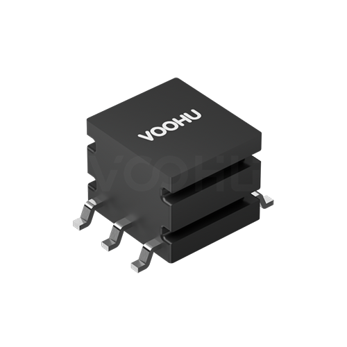 WHST06001A0 L(μH)538 Turns Ratio 1:1 DCR1 750mΩ DCR2 750mΩ Push-Pull/Driver Transformers
> View Details
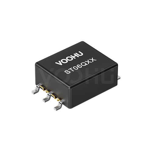 WHST06Q02E0 L(μH)86 Turns ratio 01:02.88 Isolation (VAC): 2500 Push-pull transformer
> View Details
 WHEP13779 Power 25.2W, Output voltage 12V, Output current 2.1A, Turns ratio 26:10:09; ±3% POE power transformer
> View Details