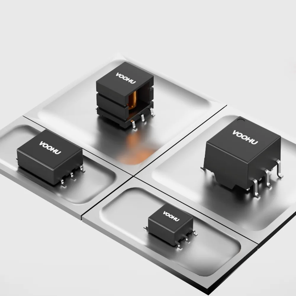
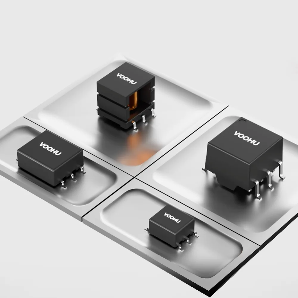
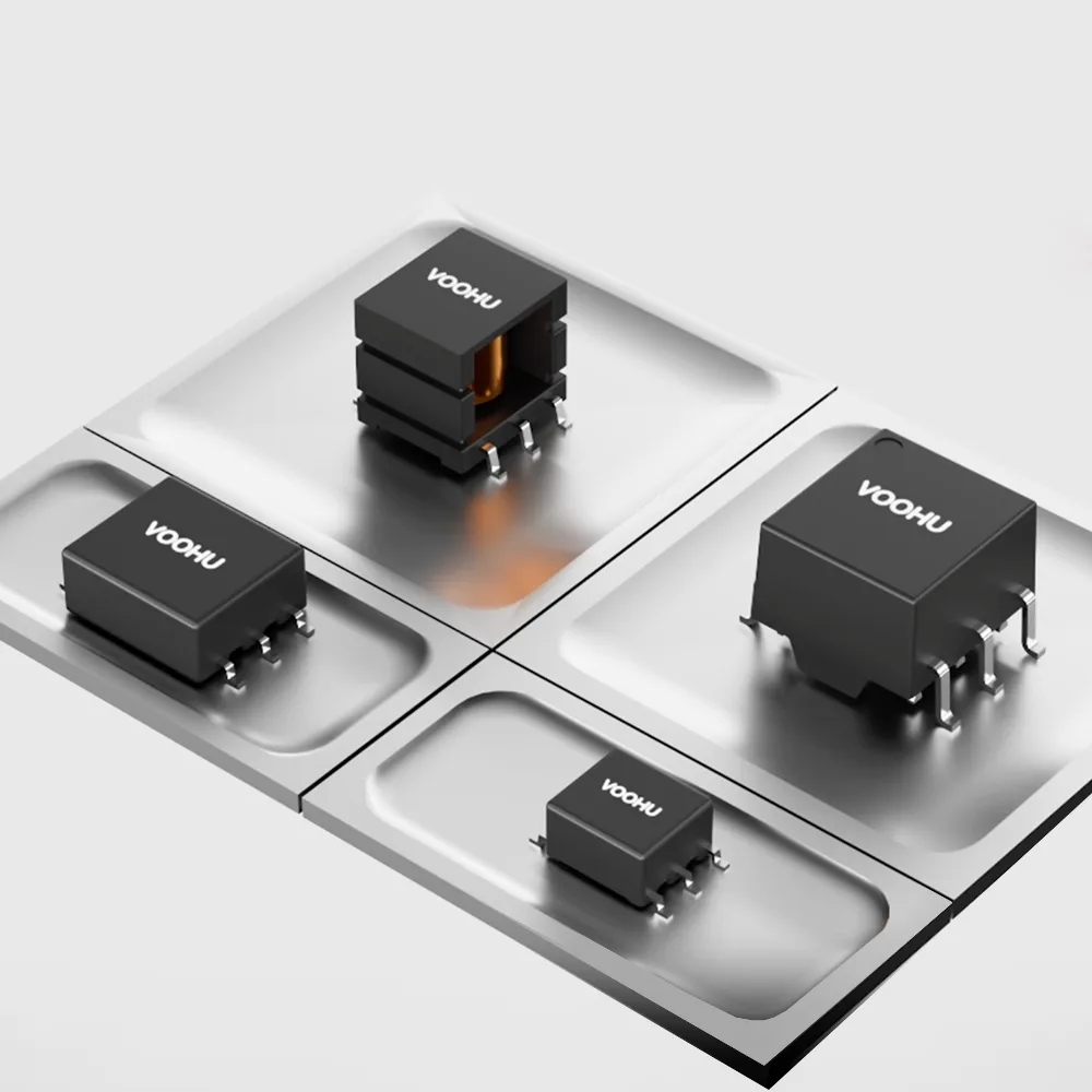
A push-pull converter is an isolated DC-DC converter that uses two switches to drive the two halves of a center-tapped transformer primary in turn. A PWM controller turns the switches on 180° apart, so the primary sees +Vin and then -Vin, and the core is magnetized in both directions. The secondary, also center-tapped, feeds two rectifier diodes and an LC filter, which turn the square wave back into DC. Each switch must stay below 50% duty cycle so that both are never on at once, and the gap between their on-times is the dead time. In the ideal case the output is about 2 × D × Vin × (Ns/Np), and each switch must block about twice the input voltage. The topology suits low input voltages and isolated auxiliary rails, where both switches can sit on the ground side.
#What are the parts of a push-pull converter?
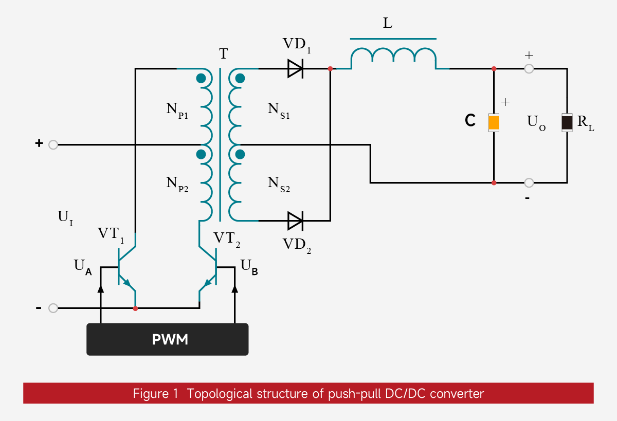
A push-pull DC-DC converter can be viewed as two single-switch forward converters that share one transformer and one output filter. Its parts are:
- Push-pull transformer (T): a primary split into two equal halves, NP1 and NP2, and a secondary split into NS1 and NS2. Both windings are center-tapped, and the winding polarities are marked with dots.
- Power switches (VT1, VT2): bipolar transistors or MOSFETs. Both are referenced to the negative input rail, which keeps gate drive simple.
- Output rectifiers (VD1, VD2): each diode conducts during one half-cycle, so current always flows into the filter in the same direction.
- Output filter (L, C): the inductor smooths current and the capacitor holds the output voltage, Uo, across the load RL.
- PWM controller: produces two complementary drive signals, UA and UB, 180° apart.
The input voltage, Ui, is connected to the primary center tap. In the formulas below, Ui is written Vin and Uo is written Vo.
#What happens in each half-cycle?
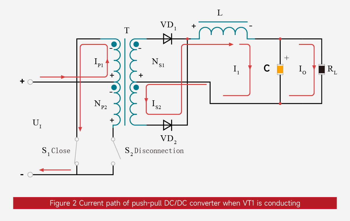
VT1 on, VT2 off. When UA is high, VT1 conducts and Ui appears across NP1. The primary current IP1 rises linearly. By induction, every winding takes the same polarity, so VD2 is forward-biased and VD1 is reverse-biased. The voltage on NS2 drives a rising current IS2 through L. That current charges C (I1) and supplies the load (Io), so IS2 = I1 + Io.
VT2 on, VT1 off. When UB is high, VT2 conducts and Ui appears across NP2 with the opposite polarity. Now VD1 conducts and VD2 blocks. The voltage on NS1 drives IS1 through L, again charging C (I2) and supplying the load, so IS1 = I2 + Io.
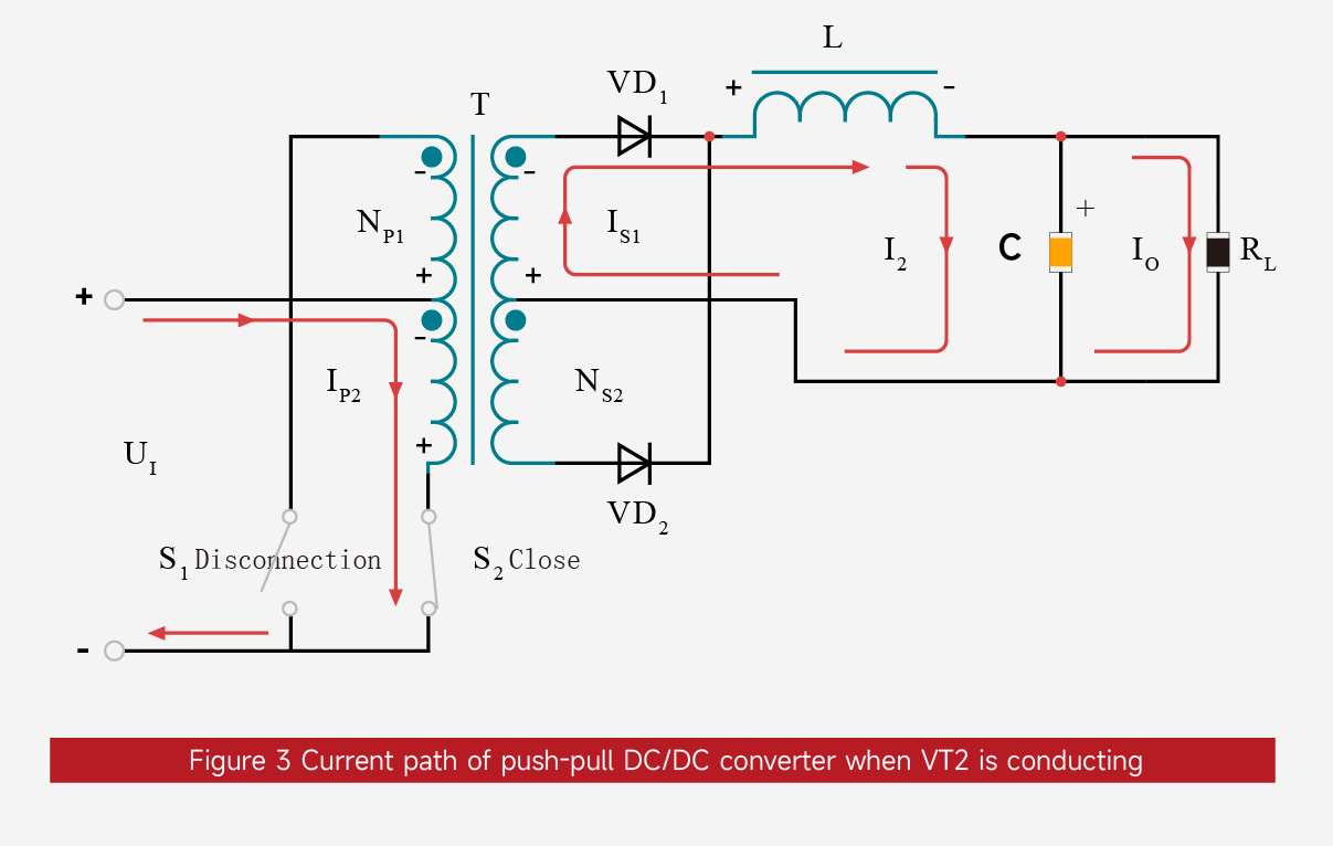
Because the two half-cycles push current through the filter in the same direction, the output ripple frequency is twice the switching frequency of each transistor.
#Why must each switch stay below 50% duty cycle?
If VT1 and VT2 conduct at the same time, the two primary halves cancel each other's flux and the input is effectively shorted through the switches. To prevent this shoot-through, the duty cycle D of each drive signal must be strictly below 50%. The interval in which both UA and UB are low is the dead time. A smaller D gives a longer dead time.
How much dead time is enough depends on the switch turn-off delay and the driver, so take the minimum from the controller and switch datasheets rather than from a rule of thumb.
During the dead time, both rectifiers share the inductor current and the transformer windings carry almost no net voltage.
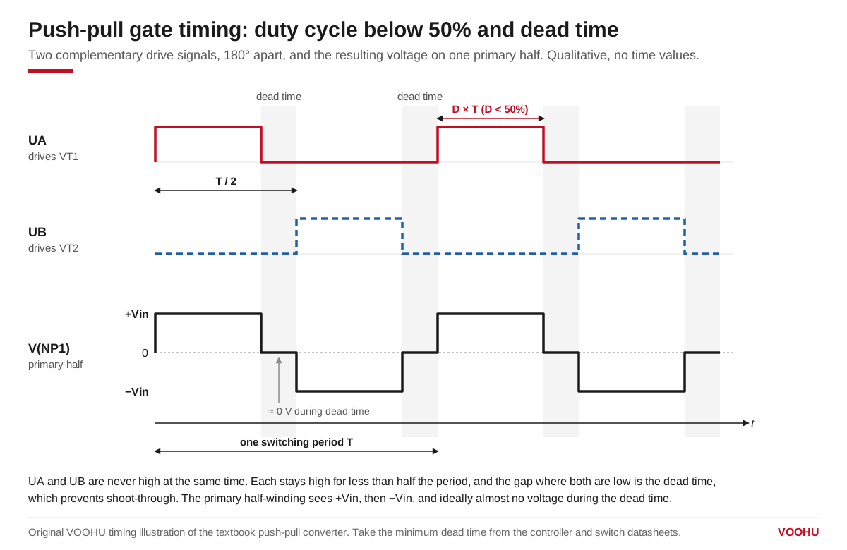
Each drive signal stays high for less than half the period; the gap where both are low is the dead time, which prevents shoot-through.
#What sets the output voltage and the switch stress?
With continuous inductor current and ideal parts, the output of a push-pull converter is:
Vo ≈ 2 × D × Vin × (Ns / Np)
where D is the duty cycle of each switch, Np is one primary half, and Ns is one secondary half. Diode drops, winding resistance and leakage inductance reduce the real output, so treat the formula as a starting point.
The off-state switch sees roughly twice the input voltage. While VT1 conducts, NP1 carries Vin, and NP2 adds the same voltage on top, so the drain of VT2 sits near 2 × Vin. Leakage inductance adds a spike on top of that. For this reason push-pull is usually chosen for low or moderate input voltages.
#What is flux imbalance in a push-pull transformer?
The core is driven in both directions, which is good for core utilization. The risk is that the two half-cycles are never perfectly equal. Small differences in switch on-time or voltage drop leave a net volt-second each cycle, and the flux "walks" toward one side until the core saturates.
Common countermeasures are current-mode control, closely matched switches and a transformer with enough flux margin. Selection details are covered in our guide to push-pull transformer selection and flux bias.
#Push-pull vs flyback, forward and full-bridge: which fits?
The values are ideal relationships; leakage spikes and diode drops come on top.
#How do you choose a push-pull transformer?
A push-pull transformer is a component, not a module. You still supply the driver, rectifiers and any regulation. Start from the input range, output voltage and load, the driver and switching frequency, and the isolation requirement. Then check turns ratio, inductance, DCR and isolation test conditions.
The table below takes one datasheet-checked part from each VOOHU WHST family on the push-pull transformer selector. Other parts in the same family can differ, so read the datasheet for your exact part number.
An isolation test voltage is not a continuous working voltage. The WHST060xxA0 datasheet, for example, pairs a 4 kVrms isolation rating with 550 Vrms continuous. Duration also changes the meaning of a figure: 2500 VAC for 60 s on the WHST06D07E0 is a different test from 2500 VAC for 1 s on the WHST06Q02E0. Read voltage, AC or DC, duration and tested pins together; for the volt-time capability, see the datasheet. For a complete circuit, see the push-pull converter solution.
#FAQ
What is the difference between a push-pull converter and a push-pull inverter?
Both drive a center-tapped transformer with two alternating switches. A push-pull inverter stops at the transformer secondary and delivers AC. A push-pull converter adds rectifiers and an LC filter to deliver DC.
Why does each switch in a push-pull converter see twice the input voltage?
When one switch conducts, its primary half carries Vin. Through the shared core, the other half carries the same voltage, and both add at the off-state switch. Leakage inductance adds a spike, so leave margin above 2 × Vin.
Can a push-pull converter run without feedback?
Yes. Some isolated auxiliary supplies drive the transformer at a fixed duty cycle just under 50% and let the output follow the input and load. If the rail needs tighter accuracy, add a regulator after the rectifier or close the loop.
Need a quote, samples or selection support?
Part number WHST06E12A0 is filled in for you. Add the quantity and lead time and submit. Our FAE team will be glad to confirm the options for your project.
Before you order: samples, MOQ, lead time and import duties in our ordering guide →