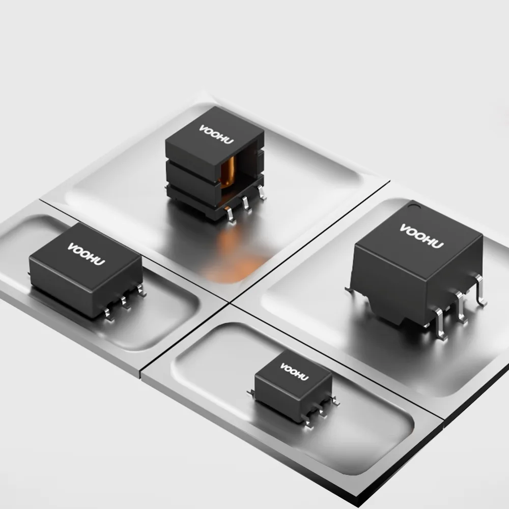
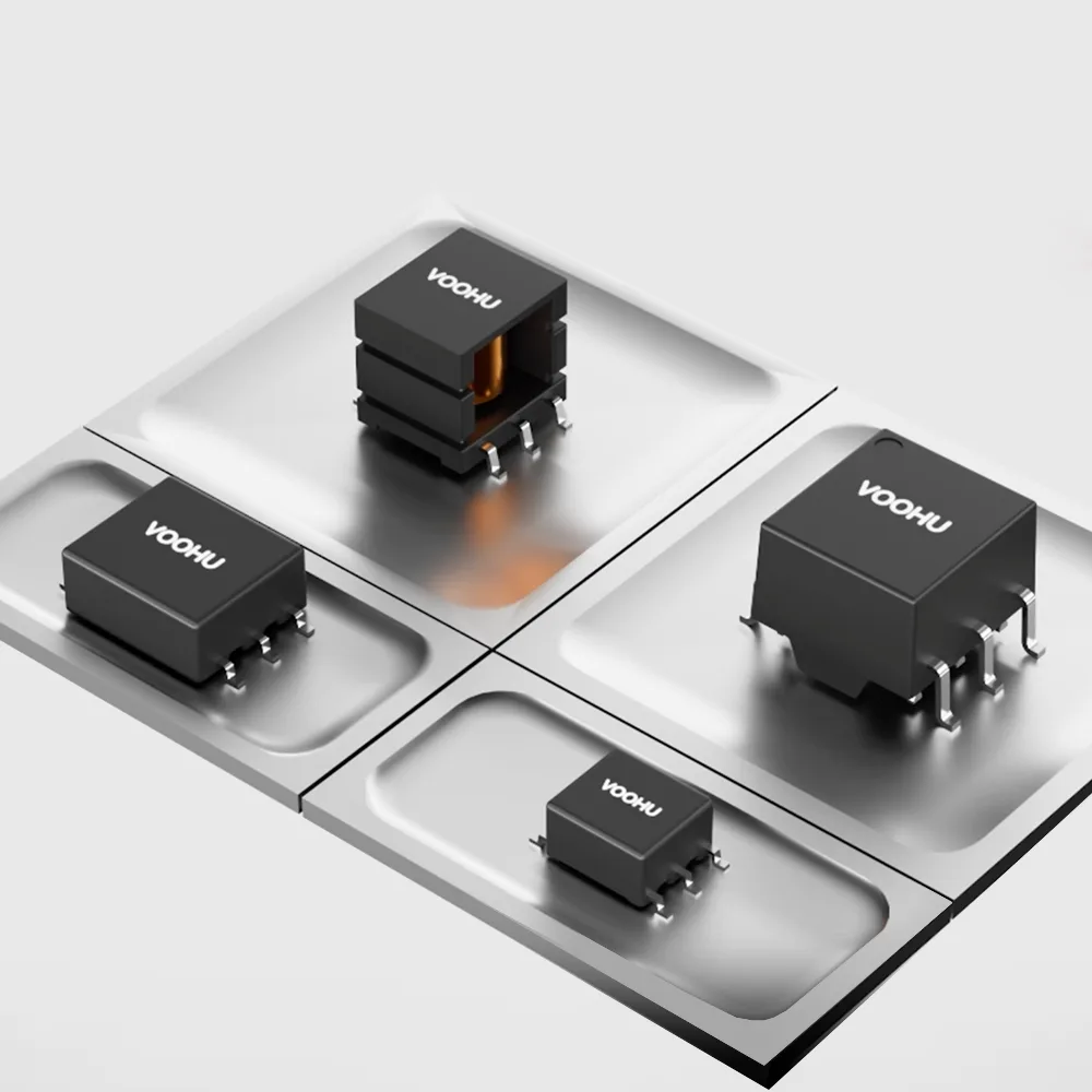
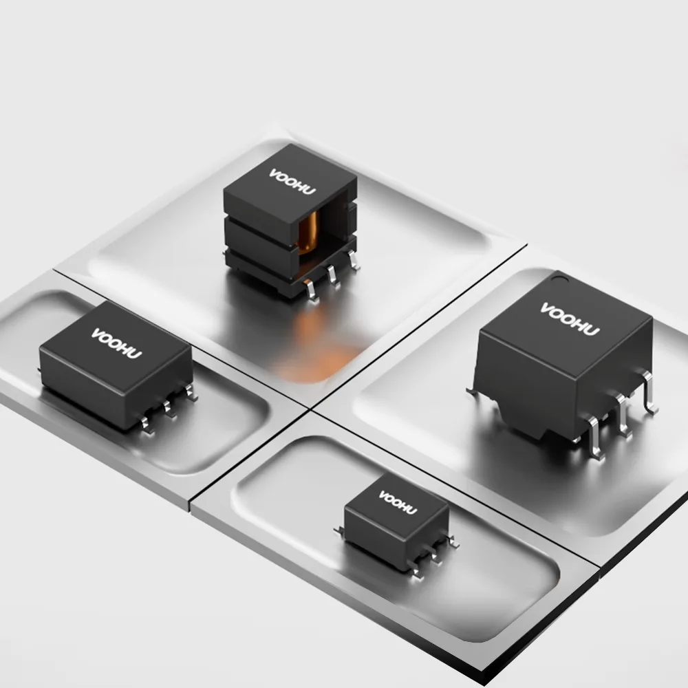
Push-pull transformer design comes down to four checks. First, set the turns ratio from the input and output voltage, allowing for the switch and rectifier drops. Second, keep the volt-seconds applied in each half-cycle below what the core can take, or it will saturate. Third, make the two half-cycles equal so the flux stays balanced. Fourth, pick the isolation rating and test condition your system needs. When you start from a standard part instead of winding your own, the core and windings are already designed, and the job becomes reading the datasheet against these four checks. VOOHU WHST push-pull transformer datasheets give the turns ratio, inductance with its test condition, and the isolation test; some also give a volt-second rating and a typical application.
#How does a push-pull transformer work?
The input voltage connects to the center tap of the primary, and two switches at the ends of the primary turn on alternately. Each switch drives current through its half of the primary, so the core is magnetized in one direction and then the other. The secondary, often center-tapped with two diodes, rectifies the resulting AC into a DC output. When one switch is off, the other half of the primary couples a voltage back onto it, so each switch sees about twice the input voltage plus any spike. The full operating cycle is explained in how a push-pull converter works; this article covers the transformer.
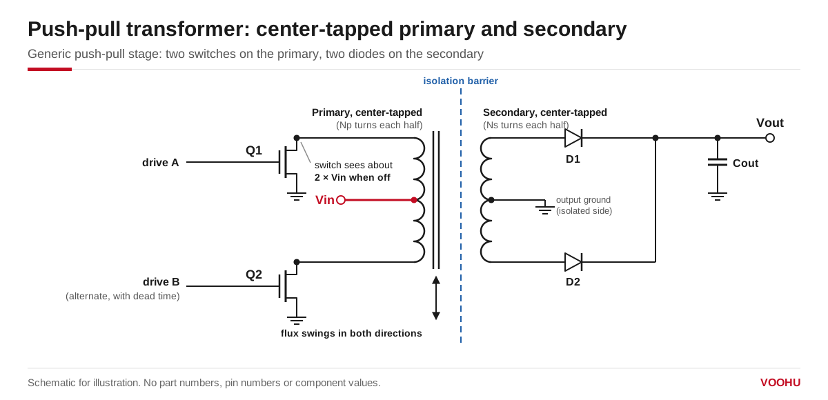
A push-pull stage: the input feeds the primary center tap, two switches conduct alternately, and a center-tapped secondary with two diodes rectifies the output across the isolation barrier.
#How do you calculate the turns ratio of a push-pull transformer?
With a center-tapped primary and a center-tapped secondary rectified by two diodes, the ideal output is the input voltage multiplied by the ratio of secondary turns to primary turns, half-winding to half-winding. In practice, subtract the switch drop on the primary and the diode drop on the secondary, and check the result at the lowest input voltage and the highest load. A bridge rectifier on a secondary without a center tap uses the whole secondary in every half-cycle, which doubles the effective ratio for the same winding.
So start from Vout ÷ Vin, add margin for the drops and for any regulator after the transformer, and pick the nearest available ratio. The WHST060xxA0 datasheet states the ratio as primary (pins 1–3) to secondary (pins 6–4) and covers ten ratios; the parts listed on this site are:
The same datasheet rates the series for 4 kVrms isolation (550 Vrms continuous), with 8 mm minimum creepage and clearance between primary and secondary and reinforced insulation to IEC 62368-1. To see every WHST060 part with its ratio, filter the push-pull transformer selector by series.
#How do you keep a push-pull transformer from saturating?
The flux in the core rises in proportion to the voltage across the winding multiplied by the time it is applied, the volt-seconds. In each half-cycle, one half of the primary sees the input voltage for the on-time of its switch. If that product exceeds what the core and turns were designed for, the core saturates, the magnetizing current climbs steeply, and the switch can be overstressed. The worst case is the highest input voltage at the lowest switching frequency.
When you design a transformer from scratch, you choose the core area, material and number of turns to keep peak flux below saturation. With a standard part, compare your worst-case volt-seconds with the datasheet rating where one is given; our FAE team can confirm how the rating applies to your circuit. For example, the WHST06Q02E0 datasheet gives a voltage-time rating of 15 V·µs and a typical application of 5 V in at 400 kHz. At 400 kHz the period is 2.5 µs, so each half-cycle lasts at most 1.25 µs, and 5 V × 1.25 µs = 6.25 V·µs, below the 15 V·µs rating. The WHST060xxA0 datasheet gives 24 or 27 V·µs maximum, depending on the part.
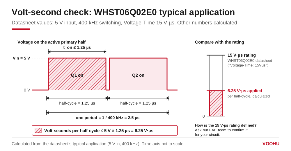
Volt-second check, calculated from the WHST06Q02E0 datasheet's typical application: 5 V applied for at most 1.25 µs per half-cycle at 400 kHz gives 6.25 V·µs against a 15 V·µs rating.
#What causes flux walking in a push-pull converter?
If the two half-cycles do not apply exactly the same volt-seconds, because of unequal on-times, switch drops or winding resistance, the flux does not return to its starting point each cycle and walks toward saturation. The transformer contributes through the symmetry of its two primary halves; the drive contributes through matched pulse widths and dead time. How to check for flux imbalance on a prototype is covered in push-pull transformer selection and flux bias.
On the winding side, three datasheet values matter besides the turns ratio. Primary inductance sets the magnetizing current, but WHST datasheets measure it under different conditions, at 10, 100 or 250 kHz and at 10 mV to 0.1 V, so compare parts only under the same condition. Leakage inductance adds to switch-node spikes; the WHST060xxA0 series is specified at 1.0 to 2.0 µH maximum. Primary-to-secondary capacitance carries common-mode noise across the barrier; the same series is specified at 15 to 30 pF maximum.
#How do you read the isolation rating?
An isolation figure only means something with its test condition, so read it as written and compare it with the test your standard or customer requires. WHST datasheets state isolation in these ways:
Do not convert between AC and DC figures or between test times yourself. If your design needs a specific voltage and duration, ask us to confirm the matching part.
#Which VOOHU push-pull transformer should you start from?
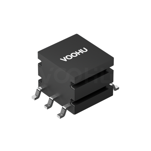
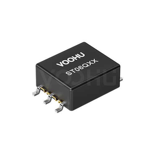
- WHST06Q02E0: a step-up ratio of 1CT:2.88CT, 86 µH minimum (at 10 kHz, 10 mV) and a 15 V·µs rating; its datasheet lists a typical application of 5 V in, 12 V and 460 mA out at 400 kHz, with values that may vary by application.
- WHST06001A0: a 1:1 ratio from the WHST060xxA0 series, which offers ten ratios in one package family with 4 kVrms isolation and reinforced insulation to IEC 62368-1.
- WHST06K14A0: a 1CT:3CT step-up, 340 µH minimum (at 100 kHz, 0.1 V), 4000 Vrms isolation hipot, and AEC-Q200 stated in the datasheet.
- WHST06D07E0: a near 1:1 ratio of 1CT:1.07CT, 600 µH minimum (at 10 kHz, 0.1 V), and isolation tested at 2500 VAC, 1 mA for 60 s.
All four are rated for operation from −40 to +125 °C. Compare the full range, with turns ratio, inductance and isolation side by side, in the push-pull transformer selector.
#FAQ
What is a push-pull transformer?
It is a transformer with a center-tapped primary driven by two switches that conduct in turn, so the core is magnetized in both directions. It is used in isolated DC/DC converters to step a DC input up or down and carry it across an isolation barrier after rectification.
What is the difference between a push-pull and a flyback transformer?
A push-pull transformer transfers energy while a switch is on and drives the core in both directions, so it is not designed to store energy. A flyback transformer stores energy in its core while the switch is on and releases it to the output when the switch turns off. The design checks differ as a result: volt-second balance for push-pull, stored energy for flyback.
Is there a push-pull transformer design calculator?
For a standard part, the calculation is short: the turns ratio from Vout ÷ Vin plus the drops, the worst-case volt-seconds from the highest input voltage and the longest half-cycle, and the isolation test your standard requires. Our FAE team can run these checks with you against WHST datasheets.
Get help choosing a push-pull transformer for your supply
Designing an isolated supply? Send your input voltage range, output voltage and current, switching frequency, driver IC and isolation requirement through our sample and support form. We can suggest a WHST turns ratio and isolation grade and check the volt-second margin with you. Samples are available for evaluation, and selected parts are free of charge. Our FAE team will be glad to confirm the options for your project. VOOHU supplies RJ45 and SFP connectors, LAN and PoE transformers and common mode chokes from Suzhou, China, to more than 1,500 customers.
Need a quote, samples or selection support?
Part number WHST06Q02E0 is filled in for you. Add the quantity and lead time and submit. Our FAE team will be glad to confirm the options for your project.
Before you order: samples, MOQ, lead time and import duties in our ordering guide →