
SFP Connector Pinout: 20-Pin Host Connector Pin Definitions for SFP and SFP+
The SFP connector pinout is the same 20-pin layout for SFP and SFP+. Pins 1, 17 and 20 are transmitter ground (VeeT), 10, 11 and 14 receiver ground (VeeR), and 15 and 16 the 3.3 V receiver and transmitter supplies. The high-speed pairs are TD± on 18 and 19 and RD± on 12 and 13. The rest are low-speed control: Tx_Fault (2), Tx_Disable (3), the two-wire bus SDA (4) and SCL (5), Mod_ABS (6), rate select (7) and Rx_LOS (8). Only pin 9 differs: receiver ground in the original SFP specification, INF-8074i, and the second rate select, RS1, in SFP+ (SFF-8431). On the host PCB, pins 1 to 10 form the row toward the bezel and pins 11 to 20 the row toward the host. VOOHU SFP+ and SFP28 connector drawings number the two rows the same way, with pin 1 and pin 20 at the same end.
What is the SFP pinout? All 20 pins with host-side connections
Names follow SFF-8431 (SFP+) with the INF-8074i (SFP) name where it differs. "In" and "out" are seen from the module.
| Pin | SFF-8431 name | INF-8074i name | Function | Host-side connection |
|---|---|---|---|---|
| 1 | VeeT | VeeT | Transmitter ground | Ground |
| 2 | Tx_Fault | TX Fault | Transmitter fault, open-drain output | Pull up to host Vcc, 4.7 to 10 kΩ |
| 3 | Tx_Disable | TX Disable | Turns the transmitter off when high or open | Module pulls it up internally (4.7 to 10 kΩ); drive low to transmit |
| 4 | SDA | MOD-DEF2 | Two-wire interface data | Pull up on the host (see FAQ Q4) |
| 5 | SCL | MOD-DEF1 | Two-wire interface clock | Pull up on the host (see FAQ Q4) |
| 6 | Mod_ABS | MOD-DEF0 | Module absent indicator; grounded inside the module | Pull up, 4.7 to 10 kΩ; high means no module |
| 7 | RS0 | Rate Select | Receive rate select (optional) | Module pulls it low internally (>30 kΩ) |
| 8 | Rx_LOS | LOS | Loss of signal, open-drain output | Pull up, 4.7 to 10 kΩ at 3.3 V (4.7 to 7.2 kΩ at 2.5 V) |
| 9 | RS1 | VeeR | SFP+: transmit rate select; SFP: receiver ground | See the SFP vs SFP+ section |
| 10, 11, 14 | VeeR | VeeR | Receiver ground | Ground |
| 12 | RD− | RD− | Receive data, inverted (out) | To the SerDes receiver |
| 13 | RD+ | RD+ | Receive data, non-inverted (out) | To the SerDes receiver |
| 15 | VccR | VccR | Receiver 3.3 V supply | Filtered 3.3 V |
| 16 | VccT | VccT | Transmitter 3.3 V supply | Filtered 3.3 V |
| 17, 20 | VeeT | VeeT | Transmitter ground | Ground |
| 18 | TD+ | TD+ | Transmit data, non-inverted (in) | From the SerDes transmitter |
| 19 | TD− | TD− | Transmit data, inverted (in) | From the SerDes transmitter |
Both specifications also fix a hot-plug order: ground pins make contact first, the two supply pins second and all signal pins last.
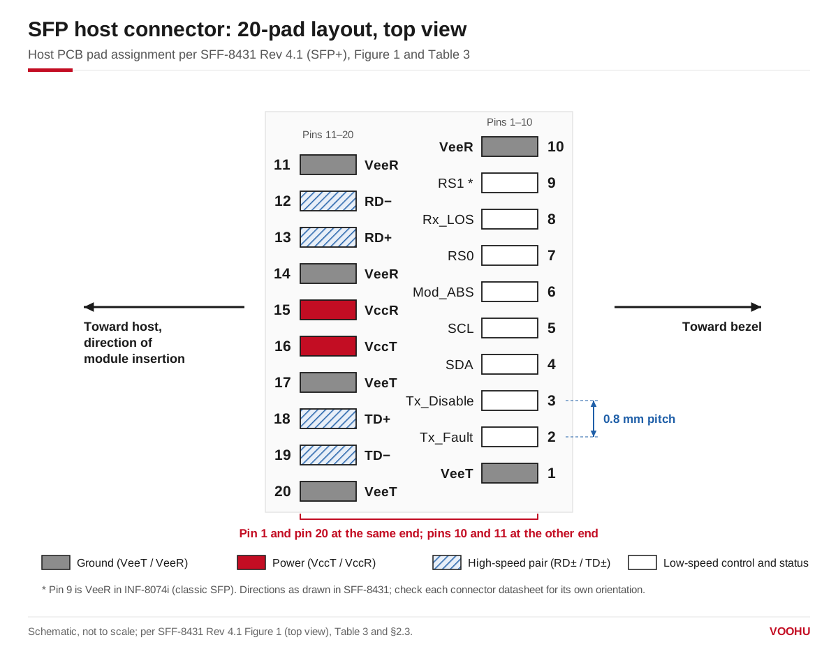
SFP host pad assignment, top view: the row toward the bezel holds pins 1 to 10, the row toward the host holds 11 to 20, and pin 1 sits at the same end as pin 20. Schematic, not to scale; per SFF-8431 Figure 1.
The SFP module pinout uses the same numbers on its edge card: contacts 1 to 10 are on the bottom of the module board and 11 to 20 on the top, so each module contact lands on the host pin with the same number. In the INF-8074i data path, the module AC-couples RD± and TD± internally and terminates TD± with 100 Ω differential, so no coupling capacitors are needed on the host board.
SFP pin layout: how are the 20 pins numbered on the PCB?
SFF-8431 specifies the SFP+ host connector as a 0.8 mm pitch, 20-position connector (the SFF-8083 improved card-edge connector) or a stacked connector with equivalent electrical performance. Its pad drawing places pins 1 to 10 in the row toward the bezel and pins 11 to 20 in the row toward the host, in the direction of module insertion, with pins 1 and 20 at one end and pins 10 and 11 at the other. INF-8074i shows the same arrangement for SFP.
VOOHU connector drawings use the same numbering. The recommended PCB layout of theWH81-151-Y0002-1, drawn as a top view, runs one row 20 to 11 and the other 1 to 10, with pin 1 under pin 20 and 0.80 mm pitch; the SFP28WHSFP30111D002and the SFP+WH290W119D0S03use the same arrangement. In the standard, pins 1 to 10 are on the bezel side; before you place the part, ask our FAE team to confirm which row of the exact VOOHU part number faces the bezel.
SFP vs SFP+ pinout: what changes?
The positions are identical; two things change.
- Names.INF-8074i calls pins 4, 5 and 6 MOD-DEF2, MOD-DEF1 and MOD-DEF0. SFF-8431 renames them SDA, SCL and Mod_ABS with the same functions.
- Pin 9 and rate select.In INF-8074i, pin 9 is VeeR and pin 7 is a single Rate Select that sets full or reduced receiver bandwidth. In SFF-8431, pin 7 becomes RS0 (receive rate) and pin 9 becomes RS1 (transmit rate), both pulled low inside the module. SFF-8431 notes that classic SFP modules commonly tie RS1 to ground, so if your host drives pin 9, make sure the driver survives seeing ground when an SFP module is plugged in.
How do you connect the Tx_Disable, Mod_ABS, LOS and rate select pins?
Values below are from SFF-8431; INF-8074i gives the same 4.7 to 10 kΩ range for SFP.
- Tx_Disable (pin 3).The module pulls this pin up to VccT through 4.7 to 10 kΩ, so the transmitter stays off when the host leaves it open. Drive it low, or ground it, to transmit.
- Mod_ABS (pin 6).The module ties it to ground. Pull it up on the host with 4.7 to 10 kΩ: high means the cage is empty, low means a module is present. If a module is not detected, ourMod_ABS and I²C troubleshooting guidewalks through the checks.
- Rx_LOS (pin 8) and Tx_Fault (pin 2).Both are open-drain outputs. Pull Tx_Fault up to the host supply with 4.7 to 10 kΩ. Pull Rx_LOS up with 4.7 to 10 kΩ on a 3.3 V host or 4.7 to 7.2 kΩ on a 2.5 V host. Rx_LOS high means the received signal is below the level the relevant standard requires.
- RS0 and RS1 (pins 7 and 9).The module pulls both low through more than 30 kΩ, so an unused rate-select pin defaults to low.
Keep every pull-up within the module's supply plus 0.5 V; SFF-8431 does not allow a higher voltage on any module contact.
What do the power pins need?
VccR (pin 15) and VccT (pin 16) are separate 3.3 V supplies for the receiver and transmitter. INF-8074i defines them as 3.3 V ±5% at the connector pin with a maximum supply current of 300 mA, and recommends an inductor-capacitor filter on each supply on the host board, which also limits inrush current when a module is hot-plugged. Because the ground pins touch first and the signal pins last, the module can be inserted with the host powered.
Which VOOHU SFP connectors use this pinout?
All three parts below follow the 20-pin numbering described above, with 0.80 mm pitch on the drawing.
| VOOHU part | Type | What the drawing shows |
|---|---|---|
| WH81-151-Y0002-1 | SFP+ connector, 20 pins | 20 solder leads; recommended PCB layout labelled top view, with the mating-board layout drawn for top and bottom |
| WHSFP30111D002 | SFP28 1×1 connector | PCB layout with pin 1 at the lower left, rows 1 to 10 and 20 to 11; tin-plated solder tails |
| WH290W119D0S03 | SFP+ 1×1 connector | Gold-plated SMT leads; reflow limit 255 to 265 °C for a maximum of 20 seconds |
To compare every SFP-family connector, open the I/O connector selector filtered toconnectors, or browse theSFPandSFP+families. For the cage that goes over the connector, see our guide toSFP+ and SFP28 cage selection; for four-lane and eight-lane ports, seeQSFP28 vs QSFP-DD vs QSFP112 vs OSFP. INF-8074i and SFF-8431 are listed in theSNIA SFF specification library.
FAQ
Q1: What does SFP connector stand for?
SFP stands for Small Form-factor Pluggable, the transceiver defined by the SFP MSA in INF-8074i. An SFP connector is the 20-pin host connector that sits inside the cage on the board and mates with the module's edge card; SFP+ uses the same pin positions, defined in SFF-8431.
Q2: Which side of SFP is transmit?
On the host connector, transmit data goes into the module on pins 18 (TD+) and 19 (TD−), in the row toward the host, and receive data comes out on pins 12 (RD−) and 13 (RD+) in the same row. Route your SerDes transmitter to pins 18 and 19 and its receiver to pins 12 and 13.
Q3: Are all SFP connectors the same?
They share the 20-pin numbering, but not every part is interchangeable. Connectors differ in the signal rate they are built for (SFP, SFP+ or SFP28), single or stacked ports, and how the cage is mounted, so choose the connector and cage together for the module generation you plan to use.
Q4: What pull-up should I use on the SFP I2C pins?
SFF-8431 pulls SDA (pin 4) and SCL (pin 5) up on the host to a 3.14 to 3.46 V supply and limits the resistor by bus capacitance and clock rate: with 100 pF of bus capacitance, at most 3.0 kΩ at 400 kHz or 8.0 kΩ at 100 kHz; with 290 pF, at most 1.1 kΩ or 2.75 kΩ. INF-8074i, for the original SFP, gives 4.7 to 10 kΩ.
Need help checking your SFP footprint and pin 1 orientation?
Send us your port requirements through thesample and support request form: SFP, SFP+ or SFP28, single or stacked, and SMT or press-fit cage. We can suggest a VOOHU connector and cage and check pin 1 orientation and the footprint against your layout. Samples are available for evaluation, and selected parts are free of charge. Our FAE team will be glad to confirm the options for your project.
VOOHU supplies RJ45 and SFP connectors, LAN and PoE transformers and common mode chokes from Suzhou, China, to more than 1,500 customers. Our connectors are made in our own factory in Dongguan.