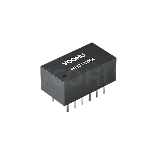
WHD12503G Single Port DIP 10/100Base-TX PIN12 non-PoE LAN Transformer


Request a Quote
Leave your details and we will send a tailored volume quote.
Our sales team will contact you within 1 business day.
Contact Sales
Reach our sales team for pricing and lead time.

Submitted
We have received your request. Our sales team will contact you within 1 business day.


For technical assistance, pleaseclick the button below to add customer service or visit the sample request pageto fill out the form. We will serve you as soon as possible.
Technical Support Email: fae.thorne@voohu.cn Phone: +86 400-1048-018
For more details, please visit theDownload Centerto get documents or click the button below to add customer service. We will serve you as soon as possible.


For purchases and small-volume orders, please contact our sales team. We support VAT general/special invoices with a convenient and efficient process.
For technical assistance or sample requests, pleaseclick the button belowto add customer service orvisit the sample request pageto fill out the form. We will serve you as soon as possible.
Customer Service Email: song.lei@voohu.cn Phone: +86 180 2130 1120
Different outline, so the hole pattern has to be redrawn: the WHD12503G body is 14.00 × 7.70 mm with 4.80 mm row spacing and stands 6.00 mm, against 13.05 × 7.80 mm, 5.00 mm row spacing and 7.50 mm Max on theWHD12401G.
This family contains both same-outline and different-outline combinations, and outline does not map one-to-one onto the internal definition, so neither alone settles a change.
The hole pattern needs no change, but the wave-solder settings should be re-checked against the new protrusion.
Leads on the WHD12503G are 3.30 mm ±0.50 mm where the rest of the family is 3.00 mm ±0.50 mm. That 0.30 mm changes how far the lead stands proud of the board, which affects joint formation and any lead-trim step downstream, and matters most on thinner boards. Hole diameter is ø0.90 mm either way, so insertion itself is unaffected. Other through-hole options sit in the10/100 BASE-T range.
Filter on hole pattern and height first, then on temperature grade. The electrical table plays no part, because it is identical across this family.
Hole patterns come in two sets: 5.00 mm row spacing with a 13.05 × 7.80 mm body, and 4.80 mm row spacing with a 14.00 × 7.70 mm body, which is where the WHD12503G sits. Parts landing on the same hole pattern do not all share an internal definition, so the hole pattern narrows the candidates rather than settling the choice. Once the shortlist is fixed, tell us the target PHY and VOOHU will help finalise it from the10/100 BASE-T range.