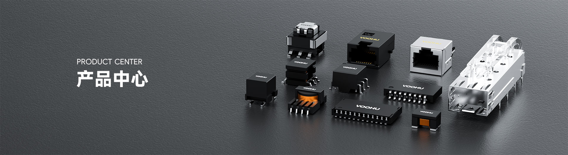
WHD20701G Dual Ports DIP 10/100Base-TX PIN20 non-PoE LAN Transformer


Request a Quote
Leave your details and we will send a tailored volume quote.
Our sales team will contact you within 1 business day.
Contact Sales
Reach our sales team for pricing and lead time.

Submitted
We have received your request. Our sales team will contact you within 1 business day.


For technical assistance, pleaseclick the button below to add customer service or visit the sample request pageto fill out the form. We will serve you as soon as possible.
Technical Support Email: fae.thorne@voohu.cn Phone: +86 400-1048-018
For more details, please visit theDownload Centerto get documents or click the button below to add customer service. We will serve you as soon as possible.


For purchases and small-volume orders, please contact our sales team. We support VAT general/special invoices with a convenient and efficient process.
For technical assistance or sample requests, pleaseclick the button belowto add customer service orvisit the sample request pageto fill out the form. We will serve you as soon as possible.
Customer Service Email: song.lei@voohu.cn Phone: +86 180 2130 1120
No — three hole patterns exist here. One is 2.54 mm pitch with 7.62 mm row spacing and a 22.86 mm span; one is 2.00 mm pitch with 7.62 mm row spacing and an 18.00 mm span, which is where the WHD20701G sits; and a third uses 2.00 mm pitch but opens the row spacing to 10.16 mm.
The Pitch field on the10/100 BASE-T rangepages carries only 2.0mm and 2.54mm, so the second and third patterns look identical in the spec table while their row spacing differs by 2.54 mm and the holes do not line up at all. Selection has to come down to row spacing and span on the drawing.
Outline, hole pattern and internal unit count are identical; the element order differs — the WHD20701G puts the common-mode choke on the chip side, theWHD20702Gon the cable side.
Both are 21.20 × 10.00 mm and 7.20 mm Max high, on 2.00 mm pitch with an 18.00 mm span and 7.62 mm row spacing, and both hold four 1CT:1CT units split between two ports. The footprint being the same, changing between them needs no PCB work; but the common-mode path has changed, so EMC has to be re-verified on the finished unit.
A 100M part, and the internal structure settles it: the WHD20701G holds four 1CT:1CT units split between two ports, two channels — one pairset — to each. That is two 100M ports.
A dual-port Gigabit device uses all four pairs per port, four channels each and eight units in total, twice as many. The product listing also classifies it under10/100 BASE-T. Where a title block disagrees with the actual rate, go by the internal unit count and the product classification.