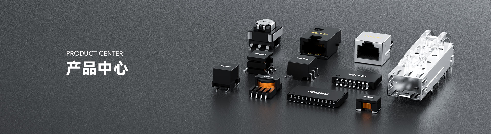
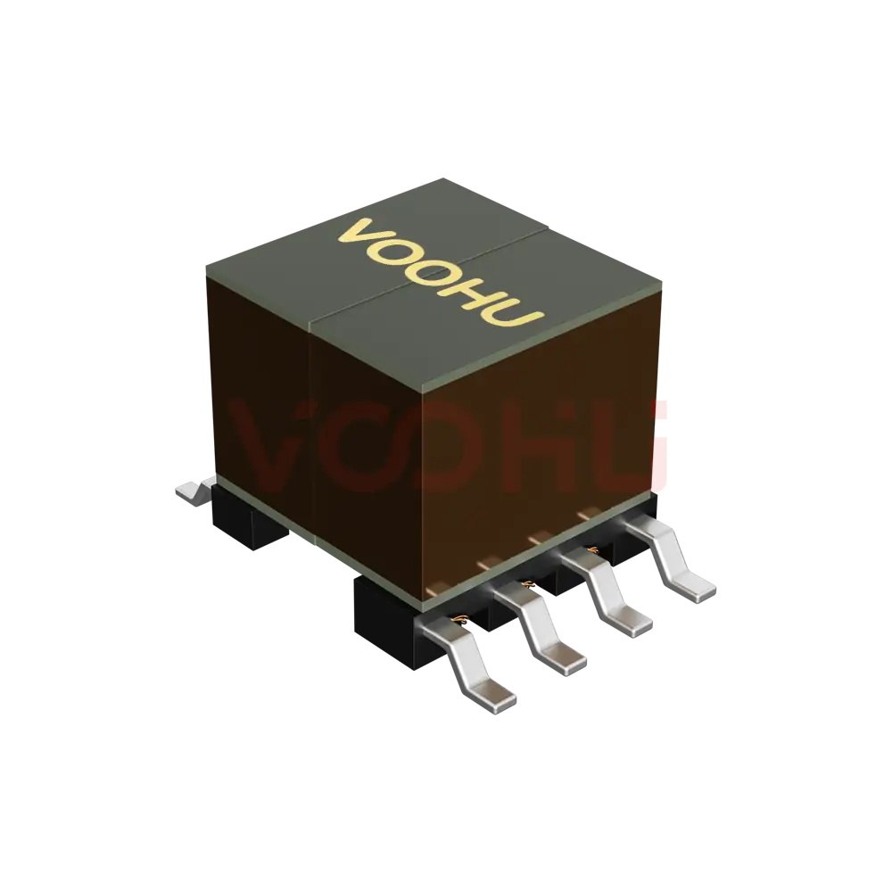
WHSG48001G Dual Ports SMD Gigabit Base-T PIN48 non-PoE LAN Transformer





Request a Quote
Leave your details and we will send a tailored volume quote.
Our sales team will contact you within 1 business day.
Contact Sales
Reach our sales team for pricing and lead time.

Submitted
We have received your request. Our sales team will contact you within 1 business day.



Für technische Unterstützung wenden Sie sich bitte an unsKlicken Sie auf die Schaltfläche unten, um den Kundenservice hinzuzufügen or Besuchen Sie die Musteranforderungsseiteum das Formular auszufüllen. Wir werden Sie so schnell wie möglich bedienen.
Technischer Support E-Mail: fae.thorne@voohu.cn Telefon: +86 400-1048-018
Weitere Einzelheiten finden Sie unterDownload-Centerum Dokumente zu erhalten, oder klicken Sie auf die Schaltfläche unten, um den Kundenservice hinzuzufügen. Wir werden Sie so schnell wie möglich bedienen.





Bei kleineren Mengen können Sie direkt auf bestellenVOOHU-Shop. Wir unterstützen allgemeine/Sonderrechnungen mit Mehrwertsteuer durch einen bequemen und effizienten Prozess.
Für technische Unterstützung oder Musteranfragen wenden Sie sich bitte an unsKlicken Sie auf die Schaltfläche untenum Kundenservice hinzuzufügen oderBesuchen Sie die Musteranforderungsseiteum das Formular auszufüllen. Wir werden Sie so schnell wie möglich bedienen.
Kundendienst-E-Mail: song.lei@voohu.cn Telefon: +86 180 2130 1120
Land pattern, the net names of all 48 pins and every electrical rating match; the only difference is which side carries the common-mode choke — on the WHSG48001G it sits on the cable side at pins 25–48 (CMT/TX), on theWHSG48002Gon the chip side at pins 1–24 (TCT/TD).
Package and pinout being identical, changing between them needs no PCB work; decide from what the PHY reference design specifies for choke position, and re-run EMC on the finished unit after a change.
Pins 1–24 are the chip side, named TD1± through TD8± with centre taps TCT1 through TCT8; pins 25–48 are the cable side, named TX1± through TX8± with centre taps CMT1 through CMT8.
Orient the WHSG48001G with pins 1–24 toward the PHY and pins 25–48 toward the RJ45 and both ports' pairs run straight through. Centre-tap net naming follows several different conventions across the100/1000 BASE-T range, so check it against this part's own drawing rather than carrying it over from another.
No. The WHSG48001G datasheet carries no PoE current item, so both ports are powered locally on the board.
The centre taps serve as AC termination and common-mode reference only, with no DC current rating, and cannot be reworked into a supply path. A port that has to deliver power over the cable needs a part rated for per-channel DC current, chosen at selection time from the100/1000 BASE-T range.