




Package size and dimensions
Stated as length by width by height in millimetres. Height is often the binding constraint, and within one footprint the taller option usually carries more current.
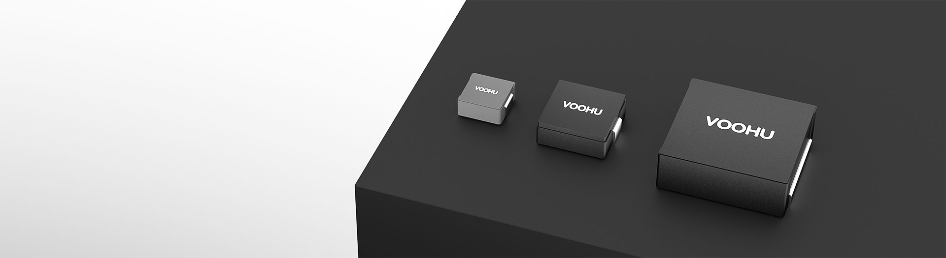
Induktivitätsprodukte
Molded construction encloses the winding in a magnetic compound, giving a self-shielded part with low audible noise and a soft saturation curve. The range runs from 4.4 by 4.2 millimetres up to 23.5 by 22, covering 0.1 to 150 microhenries and RMS currents to 70 amps.
Artikelsuche und Produktauswahl
Die Tabelle verwendet die aktuellen Produktdatensätze der englischsprachigen Website, veröffentlichte Auswahlfelder und artikelspezifische Links zu technischen Dateien.
* Spalten „Bild“ und „Artikelnummer“ fixiert · horizontal ziehen, um alle Spezifikationen anzuzeigen
| Bild | Datenblatt | Vergleichen | Downloads |
Baugröße
|
Abmessungen (L×B×H)
|
Induktivitätswert
|
DCR (mΩ)
|
IRMS
|
ISAT
|
Muster |
|---|
| Bild | Artikelnummer | Datenblatt | Vergleichen | Downloads | Baugröße | Abmessungen (L×B×H) | Induktivitätswert | DCR (mΩ) | IRMS | ISAT | Muster |
|---|---|---|---|---|---|---|---|---|---|---|---|
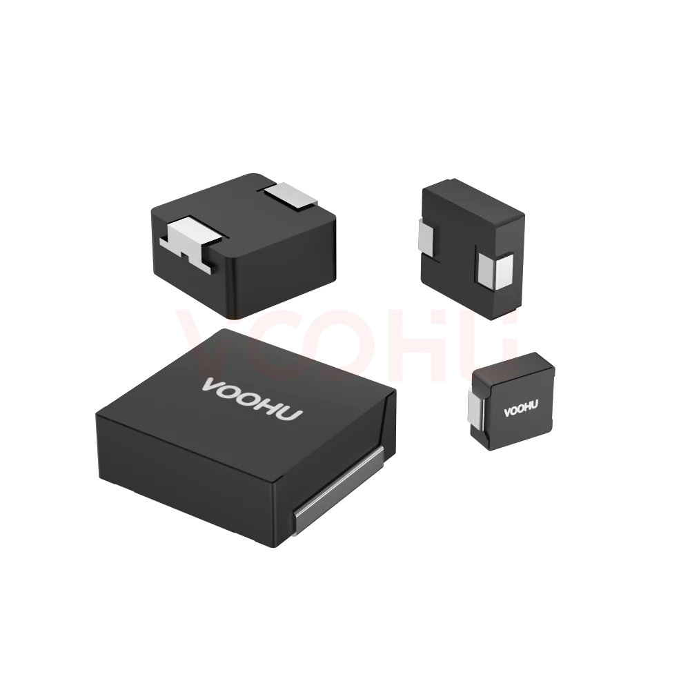 |
WHYTP0320 series | SPEC | WHYTP Serie | 3.4*3.2*1.8mm | 0.33-10uH | 21-422mΩ | 1.4-8A | 1.6-10A |
|
Erweitern Sie die ausgewählten Filter oder löschen Sie die aktuelle Suche.
By series
Series split by footprint and height, which together set current capability and loss.
So wählen Sie aus
Ripple sets the inductance; IRMS and ISAT set the size; height often decides.
Derive it from input and output voltage, switching frequency and the ripple current you can accept. Then check the tolerance band at its worst corner.
IRMS caps the continuous current by temperature rise. ISAT caps the peak by inductance roll-off. Your design has to satisfy both, not the friendlier one.
Larger footprints and taller bodies give lower DC resistance and higher current. Work back from the height clearance over the converter.
Measure ripple, efficiency and the inductor's temperature at full load in the real enclosure, then confirm at the highest rated ambient.
Parameters
IRMS and ISAT are defined differently and both have to be satisfied.
Stated as length by width by height in millimetres. Height is often the binding constraint, and within one footprint the taller option usually carries more current.
Ranges from about 0.1 to 150 microhenries across the family. Low values suit high switching frequency; higher values reduce ripple at lower frequency.
From about 0.65 milliohm on the largest low-value parts up to several hundred milliohms on the small high-inductance ones. It sets conduction loss.
The continuous RMS current producing the datasheet's stated temperature rise. It is the steady-state limit and must be derated for high ambient temperature.
The current at which inductance falls by the stated percentage. It caps the instantaneous peak, including startup inrush and load transients.
Molded construction encloses the winding in magnetic material, so the part is inherently shielded. That reduces coupling into nearby traces and lowers audible noise.
Vergleichen
Footprint and height together decide what current and inductance are available.
Zur Produktauswahl zurückkehren ↑| Baugröße | Artikelnummern | Abmessungen (L×B×H) | Induktivitätswert | DCR (mΩ) | IRMS | ISAT | Aktion |
|---|---|---|---|---|---|---|---|
| WHYT Serie | 11 | 7.0*6.6*2.8mm, 7.0*6.6*3.8mm, 7.0*6.6*4.8mm, 11.5*10*2.8mm, 11.5*10*3.8mm, 11.5*10*4.8mm, 13.45*12.6*4.8mm, 13.45*12.6*5.8mm, 13.45*12.6*6.5mm, 17.15*17.15*7mm, 23.5*22*12.6mm | 0.22-47uH, 0.68-47uH, 0.47-47uH, 0.22-33uH, 0.15-100uH, 0.22-100uH, 4.7-150uH, 4.7-100uH, 2.2-100uH, 1.00-100.00uH | 3-385mΩ, 4.8-320mΩ, 3.9-230mΩ, 0.89-160mΩ, 0.65-340mΩ, 0.8-290mΩ, 0.7-130mΩ, 9-350mΩ, 8.5-170mΩ, 2.5-130mΩ, 0.95-40mΩ | 1.5-24A, 1.8-17A, 2-20A, 4-50A, 2-45A, 2.1-37A, 3-50A, 1.5-15A, 3.5-16A, 3.7-29A, 11-70A | 2-34A, 2.5-19A, 2.6-21A, 2.6-33A, 2.3-75A, 2.8-65A, 5-75A, 2.7-24A, 4-24A, 5-34A, 9-60A | Filtern → |
| WHYTA-Serie | 7 | 4.4*4.2*1.0mm, 4.4*4.2*1.8mm, 5.4*5.2*1.6mm, 5.4*5.2*2.8mm, 7.0*6.6*1.3mm, 7.0*6.6*1.6mm, 7.0*6.6*2.2mm | 0.15-4.7uH, 0.1-10uH, 0.47-10uH, 0.1-22uH, 0.22-22uH | 9-195mΩ, 4-282mΩ, 9-155mΩ, 3-125mΩ, 8.5-175mΩ, 2.3-350mΩ, 3-230mΩ | 1.8-7.5A, 1.6-13A, 2.5-10.5A, 3.2-25A, 2-10A, 1.8-25A, 2-21A | 2.2-15A, 2-22A, 3-15.5A, 3.5-30A, 3-16A, 2.3-38A, 2.5-34A | Filtern → |
| WHYTP Serie | 1 | 3.4*3.2*1.8mm | 0.33-10uH | 21-422mΩ | 1.4-8A | 1.6-10A | Filtern → |
Anwendungsprüfung
Confirm output current, switching frequency, ripple budget and height clearance.
Documents
Datasheets carry the saturation curve, temperature rise data and land pattern.
Es werden repräsentative verfügbare Dateisätze angezeigt. Suchen Sie nach einer bestimmten Artikelnummer.
Die veröffentlichten Produktinhalte von VOOHU werden vom technischen Team geprüft. Spezifikationen, Downloads und Informationen zum technischen Support sind bestimmten Artikelnummern zugeordnet, sodass Sie sie vor einer Muster- oder Angebotsanfrage prüfen können.
Kategorieübersicht
Two questions decide most molded inductor selections: whether the construction is right for the design, and which of the two current figures limits you.
Neues Design besprechen
FAE für eine Ersatztypenprüfung kontaktieren.
Sie haben bereits eine Artikelnummer? Muster oder Angebot anfragen.
The winding is encased in a magnetic composite rather than wound on an exposed core. That makes the part self-shielding, so it couples less into neighbouring traces, and it damps the movement that causes audible buzz. It also gives a softer saturation curve, where inductance falls gradually rather than collapsing.
IRMS is a thermal limit: the continuous RMS current that produces the stated temperature rise. ISAT is a magnetic limit: the current at which inductance has dropped by a stated percentage. A design has to satisfy both. Steady-state load is checked against IRMS, and peaks including startup inrush against ISAT.
Within the same footprint, a taller body has more winding volume, which means lower DC resistance and higher current for the same inductance. The range spans from one millimetre high up to more than twelve. In practice the clearance over the converter often decides the series before any electrical parameter does.
FAQ
Answers cover molded versus wirewound, IRMS against ISAT, and shielding.
It is an inductor whose winding is encased in a magnetic composite material rather than wound on an exposed core. The construction makes the part self-shielding, reduces audible noise and gives a softer saturation characteristic. They are widely used in DC-DC converters where board space and magnetic coupling both matter.
Molded parts are self-shielded, so they couple less noise into nearby traces, and they are quieter because the winding cannot move. Their saturation curve is softer, falling gradually rather than collapsing. Open wirewound parts can offer lower cost at some sizes. Compare on DCR, IRMS, ISAT and the shielding your layout needs.
IRMS is a thermal rating: the continuous RMS current that produces the temperature rise stated in the datasheet. ISAT is a magnetic rating: the current at which inductance has fallen by a stated percentage. Both must be satisfied, IRMS for steady-state load and ISAT for peaks including startup inrush.
It depends on the load profile. A steady high current load is usually limited by IRMS and temperature rise. A load with large fast transients, or a converter with significant startup inrush, is usually limited by ISAT. Check both against your actual current waveform rather than assuming.
Start from the height clearance over the converter, because that is often the binding mechanical constraint. Within a footprint, a taller body gives lower DC resistance and higher current for the same inductance. Then confirm the band you can fit still meets both current ratings with margin.
It reduces two things. Magnetically, the enclosed winding radiates less into neighbouring traces, which helps in dense layouts. Acoustically, the encapsulation damps the winding movement that causes audible buzz at switching frequencies in the audio band. Verify both on your own assembly.
IRMS is defined for a stated temperature rise from a stated ambient. If your enclosure runs hotter or has restricted airflow, the usable current is lower. Measure the part's temperature at full load in the real enclosure at the highest rated ambient rather than trusting the headline figure.
With a complete part number, send the part number, quantity, delivery region and the date you need it. If you are still selecting, send the output current, switching frequency, ripple budget, height clearance and ambient temperature, and a sales engineer will shortlist candidates.
Technischer Support
Senden Sie die Artikelnummer des Kandidaten und die zu prüfende Bedingung. Muster können nach Abschluss der Auswahl angefragt werden; kaufmännische Fragen lassen sich im selben technischen Austausch klären.
Dokumentrevision angeben
Temperatur, Isolationsspannung und Bezugsgrundlage für den PoE-Strom
Pinzahl, Rastermaß und Abstand zwischen den Pinreihen
Zur Priorisierung von Mustern und Evaluierung
Zeitpunkt, zu dem Sie Kandidaten und einen Vergleich der Unterschiede benötigen
Die technische Prüfung ermittelt geeignete Kandidaten und erläutert die Unterschiede.
Aus der Produktauswahl oder technischen Prüfung
Prototyp / Pilotserie / Serienfertigung
Zeitplan für Muster und Serie getrennt angeben
Konformitätsnachweise, Materialdeklarationen oder Berichte Dritter
Mustermenge, Lieferzeit und Kosten hängen von der Projektphase und der Artikelnummer ab. Der Vertrieb antwortet an Werktagen.




