


Core technical specifications and risk prevention and control guidelines for network transformer wiring
Core technical specifications and risk prevention and control guidelines for network transformer wiring
(Key points for controlling the entire process of installation and debugging of high-speed Ethernet magnetic components)
As the core magnetic component of Ethernet communication system, the wiring quality of network transformer directly affects signal integrity, EMC performance and equipment life. This article systematically explains 30 key technical specifications of wiring operation from the perspective of device physical structure, circuit characteristics and engineering practice, and provides in-depth analysis solutions for typical faults.
───────────────────────────────────────────────
1. Pin definition and basic physical wiring specifications
1. Pin polarity confirmation rules
- Differential pair polarity verification: Use the beep mode of the multimeter to measure the same-name terminals:
- TX+/TX- corresponds to the same-name terminal of the primary coil (inductance value deviation needs to be <3%)
- The DC impedance of the center tap (CT) to ground should be >10MΩ (500V megohmmeter test)
- PoE power supply type needs to verify the V+/V- pin withstand voltage: 1500VAC/60s applied between the pins without breakdown
- Typical example of incorrect wiring: Due to the reverse connection of RX+/RX- on the secondary PHY side of the transformer, an industrial control device caused the 100M link negotiation to be 10Mbps, resulting in a 92% drop in network throughput. The impedance mutation point was measured by TDR time domain reflectometer and was 1.2cm away from the PHY chip. After the wiring was corrected, the rate was restored.
2. Pad and trace stress control
- Pad design:
- Use teardrop pad transition, pad diameter ≥ 2 times line width
- Creepage distance: 250V working voltage, primary-secondary spacing ≥ 2.5mm (IEC 60950 standard)
- Mechanical fixing:
- The gap between the transformer body and the PCB is controlled at 0.1mm (using silicone gasket for shock resistance)
- Pin bending radius ≥ 3 times the pin diameter to avoid metal fatigue fracture
───────────────────────────────────────────────
2. Key points of high voltage isolation and EMC protection
1. Insulation medium selection specifications

- Recommended Materials:
- Interlayer insulation: polyimide film (thickness 0.05mm, temperature resistance 400℃)
- Potting material: Epoxy resin EP310 (CTE 28ppm/℃)
2. Grounding system design
- Multi-point grounding misunderstanding: A PoE switch had a ground loop formed because the transformer housing was connected to the PGND through four grounding points, causing the radiation to exceed the standard by 15dB. After changing to single-point grounding (using the ferrite bead FB0805-601R), the EMI in the 30MHz-1GHz frequency band dropped by 22dBμV/m.
- Ideal ground topology:
Transformer shield → 1nF/2kV ceramic capacitor → ferrite bead (600Ω@100MHz) → chassis ground
↑
secondary circuit ground → 0Ω resistor ← PCB signal ground
3. Surge suppression design
- Combined protection scheme:
- Level 1 protection: Gas discharge tube (GDT) response time <100ns
- Secondary protection: TVS diode (SMBJ58CA) clamping voltage <90V
- Level 3 protection: Common mode choke (CMCC) impedance > 1000Ω@100MHz
───────────────────────────────────────────────
3. Signal Integrity Assurance Technology
1. Golden rules for differential pair routing
- Snake winding compensation: Differential pair length deviation calculation formula:
ΔL = \frac{c \cdot Δt}{\sqrt{\varepsilon_r}}
Example: FR4 board (ε_r=4.3), 5Gbps signal allows lag Δt=7ps, then ΔL_max=0.43mm
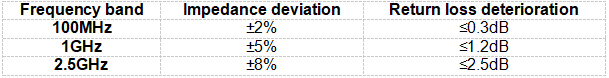
- Impedance control measured data: Conditions: line width 5mil, spacing 6mil, stacked TOP-GND spacing 4mil
2. Crosstalk Suppression Technology
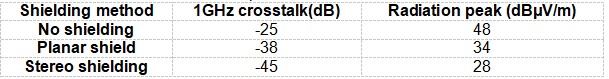
- Three-dimensional shielding structure:
- Insert 0.2mm thick copper shielding wall between TX/RX differential pairs
- Use bridging capacitors across the partitions (10pF 0402 package)
- Actual measurement comparison:
───────────────────────────────────────────────
4. Process Control List
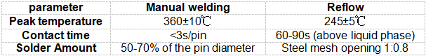
1. Welding process parameters
2. Coating and potting
- Defect case: An outdoor camera did not apply conformal coating to the root of the transformer pin. After working in an environment with 85% humidity for 72 hours, the insulation resistance dropped from 10GΩ to 5MΩ. After using polyurethane coating (Dow Corning 1-2577), it passed the IP67 certification test.
- Key points of potting process:
- Vacuum degassing treatment (vacuum degree <-95kPa, maintain for 30 minutes)
- Step curing: 60℃/2h → 80℃/4h → natural cooling
- Hardness test after curing: Shore D hardness ≥80
───────────────────────────────────────────────
5. Fault Diagnosis and Big Data Analysis*
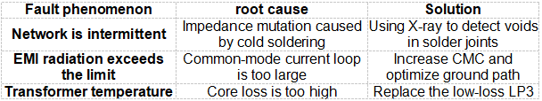
1. Typical failure mode library
2. Intelligent predictive maintenance
- Parameter warning threshold:
- Insulation resistance decrease rate>5%/month → indicates moisture risk
- Insertion loss change > 0.5dB/quarter → indicates core aging
- Coil resistance deviation>10% → indicates metal migration failure
───────────────────────────────────────────────
By strictly implementing the above technical specifications, the mean time between failures (MTBF) of network transformers can be increased from 50,000 hours to 150,000 hours. It is recommended that the engineering team establish an infrared thermal imaging inspection system for wiring processes (once a week) and use an AI visual system to automatically detect the quality of solder joints to achieve full life cycle reliability management. When deploying network equipment above 1G, use the Tektronix DPO70000 series oscilloscope to perform eye diagram testing to ensure that the signal quality after wiring meets the IEEE 802.3 standard requirements.

Newsletter subscription
Subscribe to our newsletter and stay updated on the latest information of our company and product.
Name
|
I agree that the information that I provide will be used in accordance with the terms of Voohu International Inc. Privacy & Cookies Policy


