Turns ratio and center taps
Identify the stated pins and winding sections. An abbreviated ratio is not a regulated output-voltage specification.
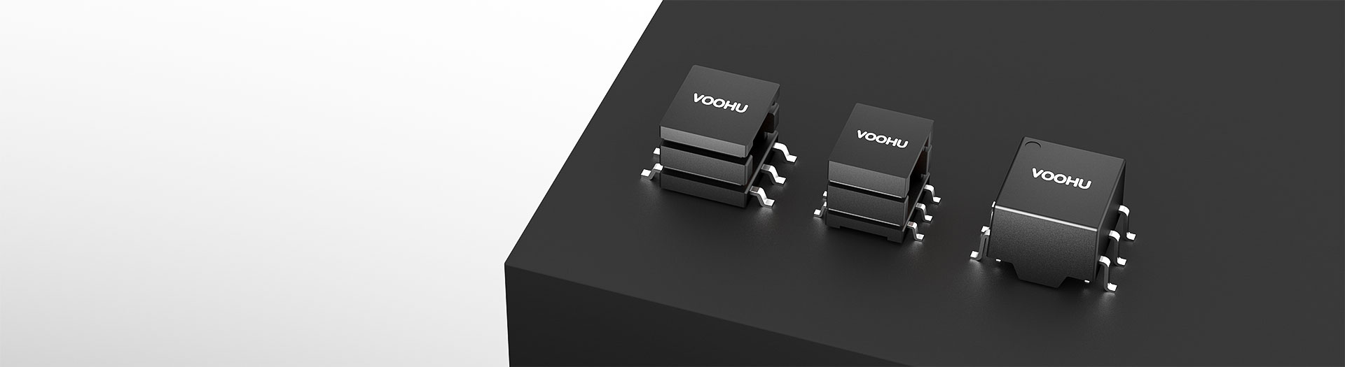
Transformer products
Compare WHST060 turns ratios, including 1:1, 1:2, 2:1 and 3:5, across A0, G0 and E0 variants. Review winding, dielectric-test and layout requirements by complete part number. Request samples or discuss selection and replacement with your sales engineer and FAE.
Part number search & selector
The table uses the current English-site product records, published selection fields and part-specific technical-file links.
* Frozen Image and Part Number columns · drag horizontally to review all specifications
| Image | Datasheet | Compare | Downloads |
Series
|
L(μH)
|
Turns Ratio
|
DCR1(mΩ)
|
DCR2(mΩ)
|
Isolation(VAC)
|
Operating Temperature(℃)
|
Sample |
|---|
| Image | Part number | Datasheet | Compare | Downloads | Series | L(μH) | Turns Ratio | DCR1(mΩ) | DCR2(mΩ) | Isolation(VAC) | Operating Temperature(℃) | Sample |
|---|---|---|---|---|---|---|---|---|---|---|---|---|
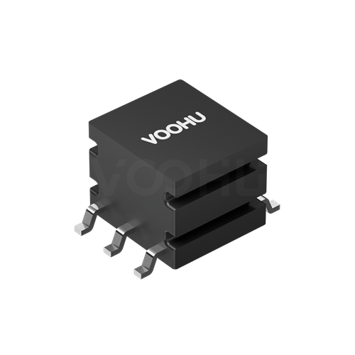 |
WHST06010A0 | SPEC | WHST060 | 538 | 1:1.7 | 750 | 1200 | 4000 | -40℃ to 125℃ |
|
||
|
|
WHST06021A0 | SPEC | WHST060 | 538 | 8:9 | 750 | 1000 | 4000 | -40℃ to 125℃ |
|
||
|
|
WHST06008A0 | SPEC | WHST060 | 538 | 8:3 | 1500 | 750 | 4000 | -40℃ to 125℃ |
|
||
|
|
WHST06007A0 | SPEC | WHST060 | 538 | 4:3 | 900 | 750 | 4000 | -40℃ to 125℃ |
|
||
|
|
WHST06006A0 | SPEC | WHST060 | 538 | 3:8 | 750 | 1500 | 4000 | -40℃ to 125℃ |
|
||
|
|
WHST06005A0 | SPEC | WHST060 | 680 | 3:5 | 750 | 1200 | 4000 | -40℃ to 125℃ |
|
||
|
|
WHST06003A0 | SPEC | WHST060 | 538 | 2:1 | 1300 | 750 | 4000 | -40℃ to 125℃ |
|
||
|
|
WHST06001A0 | SPEC | WHST060 | 538 | 1:1 | 750 | 750 | 4000 | -40℃ to 125℃ |
|
||
|
|
WHST06001E0 | SPEC | WHST060 | 340 | 1:1 | 700 | 700 | 4000 | -40℃ to 125℃ |
|
||
|
|
WHST06002G0 | SPEC | WHST060 | 340 | 1:2 | 750 | 1300 | 4000 | -40℃ to 125℃ |
|
||
|
|
WHST06003G0 | SPEC | WHST060 | 538 | 2:1 | 1300 | 750 | 4000 | -40℃ to 125℃ |
|
||
|
|
WHST06032G0 | SPEC | WHST060 | 680 | 3:4 | 750 | 900 | 4000 | -40℃ to 125℃ |
|
||
|
|
WHST06005G0 | SPEC | WHST060 | 680 | 3:5 | 750 | 1200 | 4000 | -40℃ to 125℃ |
|
||
|
|
WHST06006G0 | SPEC | WHST060 | 538 | 3:8 | 750 | 1500 | 4000 | -40℃ to 125℃ |
|
||
|
|
WHST06007G0 | SPEC | WHST060 | 538 | 4:3 | 900 | 750 | 4000 | -40℃ to 125℃ |
|
||
|
|
WHST06008G0 | SPEC | WHST060 | 538 | 8:3 | 1500 | 700 | 4000 | -40℃ to 125℃ |
|
||
|
|
WHST06021G0 | SPEC | WHST060 | 538 | 8:9 | 750 | 1000 | 4000 | -40℃ to 125℃ |
|
||
|
|
WHST06010G0 | SPEC | WHST060 | 538 | 1:1.7 | 750 | 1200 | 4000 | -40℃ to 125℃ |
|
Broaden the selected filters or clear the current search.
Product family quick links
Counts reflect the current published product data.
How to select
Narrow the published fields in sequence, compare the remaining candidates and verify the part-specific files before design-in.
Record input range, output voltage, continuous load, startup needs, available space and thermal constraints.
Identify the driver IC or circuit, operating frequency and drive arrangement, then check turns ratio, center taps and pins.
Review isolation test conditions, inductance, DCR, leakage inductance and package. Confirm the required volt-time capability in the applicable document or with engineering.
Confirm document revisions and arrange sample testing. Request pricing directly for an identified part; have the FAE compare the original and candidate parts for a replacement project.
Key selection parameters
Identify the stated pins and winding sections. An abbreviated ratio is not a regulated output-voltage specification.
Check measurement frequency, voltage and the stated minimum or tolerance. Similar values can have different test conditions.
Compare the specified winding, conditions and maximum or typical value. These figures alone do not establish power, efficiency or temperature rise.
Check AC/DC, test voltage, duration and pins together. A single test-voltage figure does not establish operating voltage or an insulation classification.
Review it against the voltage applied to the winding and its duration. Submit your drive conditions for confirmation where the part document does not provide this parameter.
Check polarity dots, center taps, dimensions and land pattern. A matching outline does not establish electrical compatibility.
Product family comparison
Use this summary as a routing step, then verify every required value in the exact part-number row and linked technical files.
Return to the selector ↑| Series | Parts | L(μH) | Turns Ratio | DCR1(mΩ) | DCR2(mΩ) | Isolation(VAC) | Operating Temperature(℃) | Action |
|---|---|---|---|---|---|---|---|---|
| WHST06E | 6 | 475 | 1:1.1, 1:1.3, 1:1.5, 1:1.7, 1:2 | 1000 | 1000 | 3000, 3100 | -40℃ to 125℃ | Filter → |
| WHST06D | 7 | 100, 200, 538, 600, 680 | 1:1.07, 1:1:3.4, 1.2:1, 1.75:1, 3:4, 3:8, 4:1 | 237, 250, 280, 350, 400 | 70, 125, 220, 290, 520, 882, 900 | 2500, 3000, 4000 | -40℃ to 125℃ | Filter → |
| WHST06K | 2 | 340 | 1:2, 1:3 | 750 | 1300, 1500 | 4000 | -40℃ to 125℃ | Filter → |
| WHST06Q | 1 | 86 | 1:2.88 | 100 | 500 | 2500 | -40℃ to 125℃ | Filter → |
| WHST060 | 18 | 340, 538, 680 | 1:1, 1:1.7, 1:2, 2:1, 3:4, 3:5, 3:8, 4:3, 8:3, 8:9 | 700, 750, 900, 1300, 1500 | 700, 750, 900, 1000, 1200, 1300, 1500 | 4000 | -40℃ to 125℃ | Filter → |
| WHST088 | 1 | 537 | 1:1:0.45:0.45 | 660 | 330 | 2100 | -40℃ to 125℃ | Filter → |
Technical performance & application fit
Application suitability is part-number specific. Treat the catalog fields as a shortlist, then confirm the design against the linked technical files.
Downloads & technical resources
Search a full or partial SKU, then open its datasheet, 3D model or PCB footprint without returning to the product table.
Showing representative available file sets. Search to find a specific SKU.
VOOHU’s published product content is reviewed by its engineering team. Specifications, downloads and technical support information are tied to specific part numbers, so you can verify them before requesting samples or a quotation.
Category overview
These parts belong inside an isolated converter, which is what separates them from a complete power module.
Discuss a new design
Contact FAE for a replacement assessment.
Already have a part number? Request samples or a quote.
A push-pull transformer provides the isolated magnetic coupling in a converter topology. It is not a finished DC-DC module: no switching controller, no rectification, no regulation. You supply those. If you need a drop-in isolated supply, buy a module; if you are designing the converter, this is the part.
The ratio between primary and secondary windings, with the input voltage and the topology, determines the output voltage before regulation. Parts with multiple secondaries have a ratio for each. Read each winding's ratio from the datasheet rather than inferring it from the part number, because notation varies between series.
Primary inductance, switching frequency and input voltage together determine how far the core is driven each cycle. Running a transformer below its intended frequency pushes the core toward saturation. Confirm the frequency range from the datasheet and verify flux margin at worst case.
FAQ & related guides
These answers guide the page workflow. Part-specific engineering limits still come from the linked technical files.
No. WHST060 is a family prefix; A0, G0 and E0 are part of the complete part number. Review each variant's datasheet, specifications and design files separately. A matching listed turns ratio does not prove interchangeability. Use complete part numbers for samples, quotations and PCB checks.
First identify the primary, secondary, pin intervals and center taps in the datasheet. Then consider the driver, input range, rectification and required load. Ratio direction matters, and final output is not simply input multiplied by turns ratio. Send a schematic for FAE review if the connections are unclear.
No. Family documentation includes both minimum-inductance and tolerance-based specifications. Read the test frequency, measurement voltage and tolerance for the complete part number. Also check winding arrangement, DCR, volt-second requirements and isolation. Equal inductance numbers do not establish equal drive conditions or design limits.
No. Dielectric withstand is a test specification under stated conditions, not the system's continuous working-voltage rating. For the selected part, check test duration, leakage-current conditions, insulation structure and applicable operating conditions. Ask the FAE to help verify project-specific insulation requirements and documentation.
Provide the original part and datasheet revision, input/output conditions, frequency, load and PCB drawing. Your sales engineer coordinates FAE candidate matching and difference assessment. Do not order a similar suffix on the assumption of compatibility. Once the full part is confirmed, request samples or a quote directly.
Engineer support
Send the candidate part number and the condition you need reviewed. Sample support can be added after the selection is clear; commercial questions may be discussed in the same engineering conversation.
Include the document revision
Temperature, isolation voltage and PoE current basis
Pin count, pitch and spacing between pin rows
To help prioritize samples and evaluation
When you need candidates and a comparison of differences
Engineering review identifies candidate parts and explains the differences.
From the selector or engineering review
Prototyping / pilot build / production
Specify sample and production timing separately
Compliance documents, material declarations or third-party reports
Samples are free of charge. Sample quantity and lead time depend on the part number and project stage. Sales will respond on business days.