


Ethernet Circuit Design Guide
Overview of Ethernet Interface Hardware Architecture
A typical Ethernet hardware interface consists of the following parts:
- CPU/MCU: Main control system, responsible for upper-layer protocol processing.
- MAC (Media Access Control): Media access control layer, handles the encapsulation and verification of data frames.
- PHY (Physical Layer): Physical layer interface, which converts the digital signal output by MAC into an analog electrical signal.
- Network transformer (Magnetics): Provides signal isolation, common mode interference resistance and impedance matching functions.
- RJ45 interface: physical connection point, enabling connection to Ethernet physical media.
As the integration level increases, more and more SoC (System on Chip) chips have integrated MAC, and even some have integrated PHY, and the design methods are constantly being optimized.
- Analysis of key components
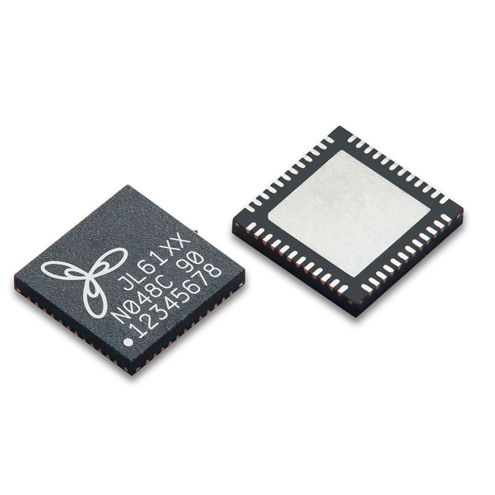
- PHY chip
- Function: Convert the digital signal of MAC layer into analog signal suitable for transmission over network cable.
- Key parameters:
- Speed: 10/100Mbps (100M), 1000Mbps (1G).
- Interface type: MII/RMII/GMII (communication with MAC).
- Transmission distance: Gigabit Ethernet supports twisted pair transmission up to 100 meters.
- Special function: Some PHY chips support POE (Power over Ethernet).
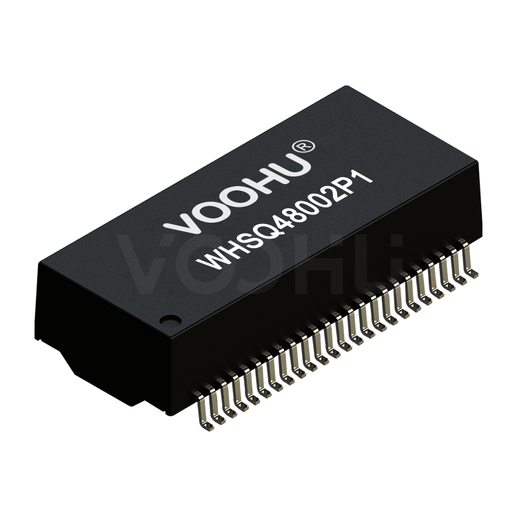
(ii) Network transformer
- Function:
- Electrical isolation: blocks the DC component between PHY and RJ45 to protect the chip.
- Suppression of common mode interference: Reduces external electromagnetic interference (EMI).
- Impedance matching: optimizes signal transmission quality.
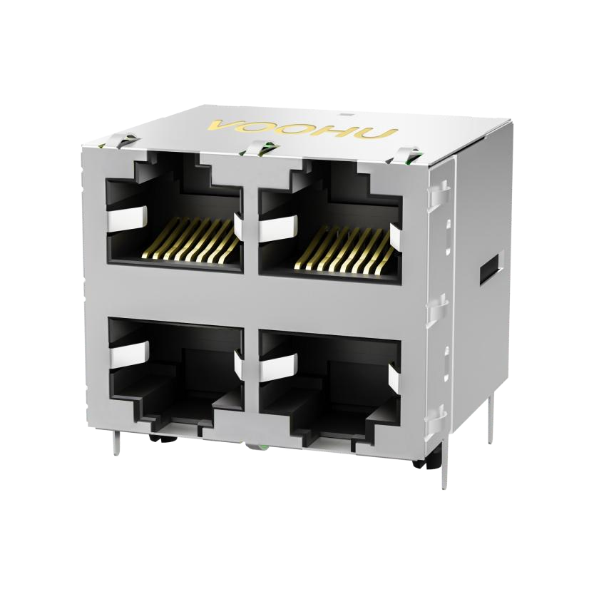
(III) RJ45 interface
- 100M (100BASE-TX): Only 2 pairs (4-core) of twisted-pair cables are used (1-2, 3-6 pairs in Cat5 or higher specification cables), 1 pair is used to send data, 1 pair is used to receive data, and the remaining 2 pairs are not used.
- Gigabit (1000BASE-T): Use all 4 pairs (8 conductors) of twisted-pair cable (Cat5e or higher).
- Key points of PCB design
- Overall layout
- Keep it as close to RJ45 as possible and shorten the differential trace length.
- Avoid other signal lines below to prevent interference.
(II) Differential line (TX/RX) routing rules
- Equal length matching (length difference required ≤ 5mil).
- Impedance control (typically 100Ω differential impedance).
- Avoid sharp-angle routing to reduce signal reflections.
(III) Key points of network port and transformer PCB design
- Withstand voltage isolation: The isolation area in the middle of the network transformer must be wide enough to ensure withstand voltage requirements. PHY and RJ45 must be on different ground planes, and cross-plane layout or routing is prohibited.
- Anti-interference processing: All layers below the transformer are hollowed out to prevent the bottom copper foil from introducing noise.
- Differential line routing: Prioritize the bottom layer, away from the network port shell ground layer. The impedance is recommended to be controlled at 100Ω±10% (not mandatory but recommended).
- Casing grounding: The grounding wire of the metal casing of the network port needs to be thickened to ensure a low-impedance connection.
- Interface protection design
- ESD protection devices: used to prevent electrostatic discharge from causing damage to subsequent circuits.
- Surge protection device: used to prevent surge voltage generated by lightning strikes and other factors from damaging the circuit.
- Practical application case analysis
Taking an industrial automation device as an example, its Ethernet interface design uses a SoC chip that integrates MAC and PHY, and achieves stable and reliable communication through reasonable layout and routing. In actual applications, the device can work stably in complex electromagnetic environments, meeting the high requirements of industrial automation for Ethernet communication.


Newsletter subscription
Subscribe to our newsletter and stay updated on the latest information of our company and product.
Name
|
I agree that the information that I provide will be used in accordance with the terms of Voohu International Inc. Privacy & Cookies Policy


