


Troubleshooting Guide for Ethernet Communication Anomalies: In-depth Analysis of PHY and Network Transformer Selection and Wiring Design Issues
Troubleshooting Guide for Ethernet Communication Anomalies: In-depth Analysis of PHY and Network Transformer Selection and Wiring Design Issues
——Locate link failures from the source of hardware design
────────────────────────────────────────────────
1. Analysis of common abnormal phenomena in Ethernet communication and their relevance to design
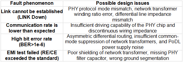
Ethernet communication anomalies usually manifest as failure to establish links, frequent packet loss, rate degradation, high bit error rate, and excessive EMI interference. Most of these problems are directly related to the selection of PHY chips, network transformer (net transformer) configuration, and wiring solutions in hardware design.
Table of typical abnormal phenomena and design defects
────────────────────────────────────────────────
2. Communication failure caused by incorrect PHY chip selection
The PHY chip is the core of the physical layer. Improper selection may lead to problems such as protocol compatibility and signal quality.
1. Protocol standards do not match
- Example: Industrial equipment uses a 10BASE-T1L PHY chip (such as ADI ADIN1100), but the network transformer only supports 100BASE-TX (1:1 turns ratio), resulting in signal coupling failure.
- Troubleshooting steps:
- Confirm the protocols supported by PHY (IEEE 802.3cg/802.3bw, etc.).
- Check whether the network transformer frequency response covers the target frequency band (for example, 10BASE-T1L needs to support 1-16MHz).
- Solution: Replace with a broadband network transformer (such as Halo TG110-E055N5, supporting 1-100MHz).
2. Power supply and level compatibility issues
- Case: The I/O voltage of the PHY chip is 1.8V, but it is connected to a 3.3V MAC controller, resulting in insufficient signal amplitude.
- Key parameter verification:
- The VDDIO voltage (1.8V/2.5V/3.3V) of the PHY must be consistent with that of the MAC controller.
- The PHY drive current (such as 20mA vs. 10mA) determines the signal transmission distance.
- Debugging tool: Use an oscilloscope to measure the TX+/- differential amplitude (standard: ±1V peak-to-peak).
3. Insufficient temperature and ESD protection
- Case: The automotive PHY chip (such as TI DP83TC811S-Q1) does not meet the AEC-Q100 Grade 2 certification and crashes in high temperature environments.
- Design points:
- Industrial-grade PHY needs to support -40℃~+125℃, and automotive PHY needs to pass AEC-Q100 certification.
- Add TVS diodes (such as Bourns CDSOT23-SM712) at the PHY interface to enhance ESD protection (≥±8kV contact discharge).
────────────────────────────────────────────────
3. Network transformer selection and wiring design defects
The network transformer is responsible for signal coupling and isolation. Design errors will directly cause signal distortion and interference.
1. Wrong winding turns ratio

- Verification method: Use an LCR meter to measure the primary/secondary inductance of the grid transformer (the inductance error of a standard 1:1 transformer is less than 5%).
2. Shielding and grounding design errors
- EMI exceeding standard case: A 360° terminated shielded transformer (such as Pulse HX5008NL) is not used, and the secondary side is not grounded through a Y capacitor, resulting in common-mode noise coupling to the cable.
- Solution:
- Choose a fully shielded transformer (metal casing + magnetically wrapped wire).
- The secondary side of the grid transformer is connected to the metal casing through a 1nF Y capacitor (grounding impedance < 1Ω).
3. PoDL power supply design flaw
- Typical fault: PHY supports Class 4 PoDL (60W), but the network transformer does not have an integrated DC isolation function, resulting in power and data conflicts.
- Compliant design:
- Use a transformer with a center tap (such as Bourns SM453230) and add a 100μF energy storage capacitor to the tap.
- Use a current clamp to measure the PoDL line current to ensure that it does not exceed the chip limit (e.g. 60W corresponds to 1.2A@50V).
────────────────────────────────────────────────
4. Key issues and corrective measures for wiring design
1. Differential routing design errors
- Impedance mismatch:
- Phenomenon: The differential line impedance is not controlled (target 100Ω±10%), resulting in signal reflection.
- Correction: Use SI9000 to recalculate the line width/spacing and adopt the "microstrip line + ground copper foil" structure.
- Unequal lengths:
- Standard: The length error within the differential pair is ≤5mm, and the error between external groups is ≤25mm.
- Tools: Enable long features like xSignals in PCB design software such as Altium.
2. Decoupling capacitor layout error
- Example: The distance between the 0.1μF capacitor near the PHY power pin is greater than 5mm, and high-frequency noise is coupled to the signal line.
- rule:
- Place a 0.1μF+1μF capacitor on each power pin (spacing ≤2mm).
- Use low ESR ceramic capacitors (such as X7R/X5R material).
3. Isolation zone design flaws
- High-voltage breakdown risk: The PHY side (DGND) and the network transformer isolation side (PGND) do not maintain sufficient creepage distance.
- Safety requirements:
- Primary/secondary isolation voltage ≥1500Vrms (industrial) or 2500Vrms (automotive).
- The width of the isolation area on the PCB is ≥3mm (reinforced insulation) and grooves are provided to prevent leakage.
────────────────────────────────────────────────
V. Actual combat case: EMC exceeding the standard and communication intermittent comprehensive failure
1. Fault phenomenon
- In an EMC test, an industrial PLC module exceeded the CE RE limit (120MHz frequency band exceeded the limit) and communication was intermittent.
2. Design Check
- PHY selection: ADI ADIN1300 (industrial grade, supports 10/100Mbps).
- Network transformer model: HX5008NL (isolation voltage 2500Vrms).
- Wiring Problems:
- The difference in differential line length is 12mm (>5mm standard), and no common mode choke is added.
- The secondary of the grid transformer is not grounded and the power decoupling capacitor is missing.
3. Corrective measures
- Optimize routing: re-layout the differential lines (reduced the length difference to 3mm) and add a common-mode filter (Murata DLW43SH101XK2).
- Grounding reinforcement: Add a 1nF Y capacitor to the metal casing on the secondary side of the transformer.
- Power supply filtering: A 100MHz ferrite bead (TDK MMZ1608S102A) is connected in series to the 3.3V power input of the PHY.
4. Test Results
- The EMC radiation value dropped by 15dB, and the communication bit error rate dropped from 1e-5 to <1e-8.
────────────────────────────────────────────────
VI. Design Verification and Debugging Toolbox
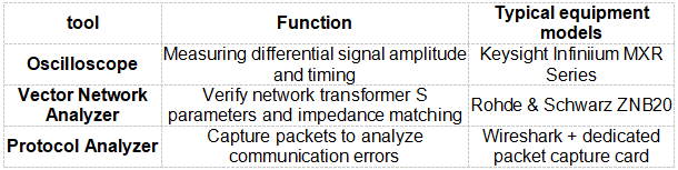
1. Hardware testing tools
2. Debug Checklist
- [ ] PHY registers are configured correctly (speed, duplex mode, auto-negotiation).
- [ ] Network transformer turns ratio matches the protocol.
- [ ] Differential line impedance complies with 100Ω±10%.
- [ ] The layout of power supply decoupling capacitors complies with the “proximity principle”.
- [ ] The secondary side of the grid transformer is grounded through a Y capacitor.
────────────────────────────────────────────────
By accurately locating the design defects of PHY and network transformers, Ethernet communication anomalies can be systematically resolved. Hardware engineers need to strictly match parameters during the selection phase and implement high-speed design rules in Layout to avoid communication risks at the source.

Newsletter subscription
Subscribe to our newsletter and stay updated on the latest information of our company and product.
Name
|
I agree that the information that I provide will be used in accordance with the terms of Voohu International Inc. Privacy & Cookies Policy


