


【Basic Product Introduction】Wohu Electronics' common mode inductors for signal lines and power lines create a dual EMC barrier for your equipment.
Known as the "noise filter" in electronic systems, common mode chokes play an indispensable role. However, many engineers often face confusion during selection: what exactly differentiates common mode chokes used in signal lines from those in power lines? And what consequences might arise from an incorrect selection? Today, the FAE team at Voohu Electronics will take you through an in-depth analysis of the secrets behind these two types of common mode chokes, helping you achieve precise selection and effectively enhance your product's EMC performance.
I. Same Mission, Different Battlefields: Consistency in Core Functions?
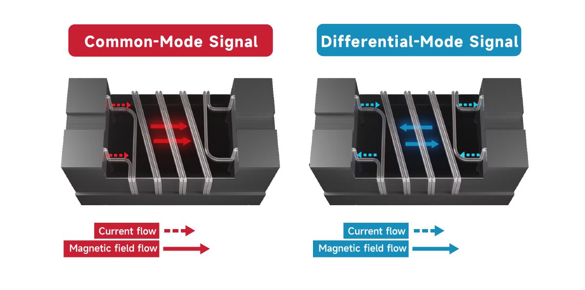
First, clarify the core functions: The core goal of both types of common-mode inductors is to suppress common-mode noise. They utilize two sets of coils wound on the magnetic core (with opposite differential-mode current paths), presenting high impedance (inductive reactance) to common-mode currents that flow in the same direction to form an obstruction; while presenting low impedance to differential-mode currents (useful signals or power supply currents) that flow in opposite directions, allowing them to pass smoothly. This serves as the fundamental working principle shared by both.
Common-Mode Signal
When the common-mode component of a signal attempts to pass through a choke coil, it encounters a high impedance. This is caused by the inductance generated by the magnetization of the core and the coil.
Differential-Mode Signal
In contrast to the common common-mode behavior, the differential-mode component of the signal encounters almost no impedance in the choke coil. This phenomenon can be explained by the magnetic field compensation inside the magnetic core. If the magnetic core is not magnetized, no inductance will be present in the circuit.
Ⅱ. Key Differences: Stemming from Stringent Requirements of Application Scenarios
Although the objectives are consistent, the significant differences in application scenarios determine their notable distinctions in terms of design, materials, and performance parameters:
Signal Line Common Mode Choke
Application Scenarios:
Data transmission lines such as Ethernet, CAN, RS485, USB, and LVDS.
Core Challenges:
Fidelity as the Top Priority: The primary task is to transmit high-speed digital signals or analog signals with extremely low distortion. Any degradation of the signal waveform (rise/fall time, overshoot, ringing) is unacceptable.
High-Frequency Noise: The main focus is on combating high-frequency common-mode noise (such as switching noise, radio frequency interference) at the MHz or even GHz level.
Low Current:The differential-mode current flowing through is usually small (ranging from mA to several hundred mA).
Miniaturization: Space is often limited, requiring a high degree of integration.
Design Features:
Magnetic Core Material:Materials with excellent high-frequency characteristics and extremely low loss are mostly used, such as Nickel-Zinc Ferrite (NiZn Ferrite). Such materials can still maintain high initial permeability and impedance in the MHz-GHz frequency band.
Coil Structure: The number of winding turns is relatively small, and the design optimizes distributed parameters (parasitic capacitance, leakage inductance) to the greatest extent, so as to minimize the impact on signal integrity (e.g., reducing insertion loss, ensuring impedance matching). Structures with precise winding and good symmetry (such as bifilar winding) are commonly used.
Key Parameters:
Impedance-Frequency Characteristic: It is required to have high and flat common-mode impedance in the target noise frequency band (e.g., 2.5GHz for USB 3.0, GHz range for HDMI).
Insertion Loss:Must be extremely low (usually less than a few tenths of a dB in the target signal frequency band) to ensure the signal passes through with almost no loss.
Bandwidth: Needs to cover the fundamental frequency of the signal and its high-order harmonics.
Rated Current: Relatively small, but must meet the requirements of signal lines.
Size: Miniaturization and surface mount (SMD) are the mainstream.
Voohu Electronics provides a full range of dedicated signal chip common-mode inductors for high-speed interfaces (Ethernet, CAN, RS485, USB, LVDS). These inductors adopt high-performance NiZn magnetic cores and precision winding technology, which strictly ensure signal integrity (low insertion loss, excellent S-parameters) while delivering outstanding high-frequency noise suppression capability.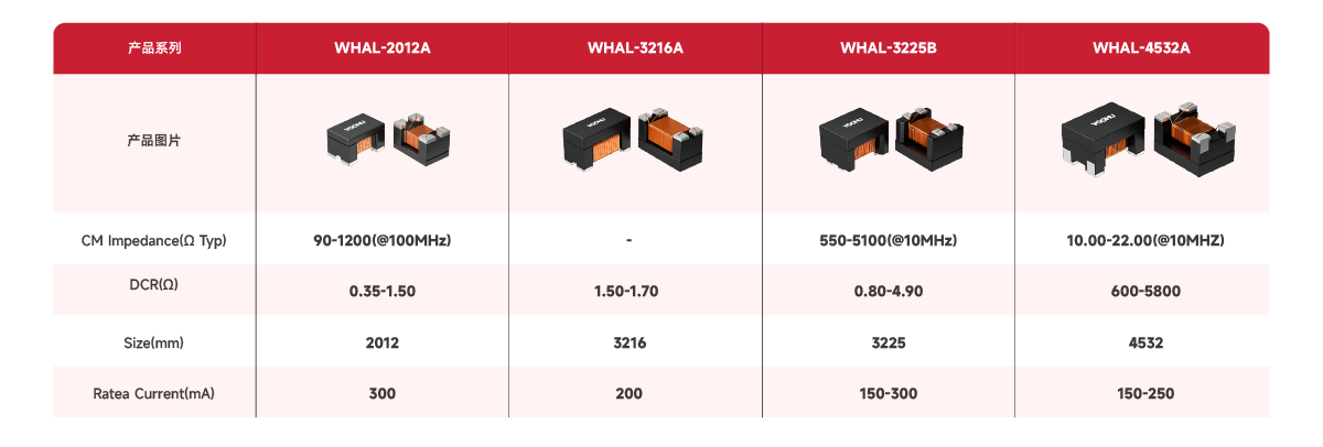
Power Line Common Mode Choke
Application Scenarios: Power supply lines at the input/output terminals of DC/DC converters in industrial automation, motor drives, inverters, BMS (Battery Management System), etc.
Core Challenges:
High Current Carrying Capacity: Required to withstand ampere-level differential-mode current, and the current may contain a DC component.
Wide-Frequency Noise: The frequency range of common-mode noise that needs to be suppressed is very wide, which may exist from tens of kHz (switching power supply fundamental frequency) to MHz (switching harmonics).
Safety and Reliability: Must meet strict safety regulations, with high insulation withstand voltage and flame retardant rating. Magnetic core saturation is a major risk point.
Low Heat Generation: Under high current, losses (copper loss + core loss) must be controlled, and temperature rise should be low.
Design Features:
Magnetic Core Material: Mainly uses materials with high saturation flux density (Bs), low loss, and good DC bias characteristics.
Coil Structure: The winding adopts thicker enameled wire to reduce copper loss and carry high current. The structure places more emphasis on heat dissipation and mechanical strength.
Key Parameters:
Rated Current: One of the most important parameters, which must be greater than or equal to the maximum operating current of the line (including peak value), and temperature rise derating should be considered.
DC Resistance: Must be sufficiently low to reduce power loss and voltage drop.
Impedance-Frequency Characteristic: Requires sufficient high common-mode impedance in the main interference frequency band (e.g., 150kHz-30MHz).
Rated Voltage/Safety Certifications: Must comply with the insulation level and safety standards required by the application.
Saturation Current: Must be much higher than the possible instantaneous peak current (including DC bias) to prevent magnetic core saturation and failure.
Size/Heat Dissipation: Usually large in volume, and heat dissipation design may be required.
Advantages of Voohu Electronics:
Voohu Electronics' power common-mode inductor series selects magnetic cores with high saturation flux density, adopts a low DCR (Direct Current Resistance) design and optimized heat dissipation structure, and provides a wide range of rated currents (from milliamps to amps). We pay special attention to the design of high saturation current and low loss characteristics to ensure the high efficiency, stability and safety of the power supply system.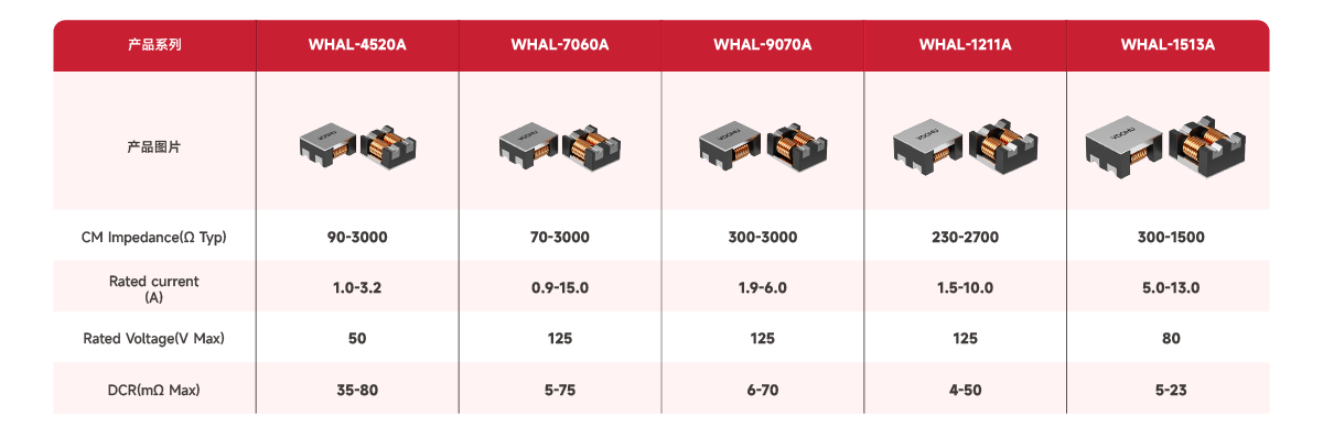
Voohu Electronics: From Inception to Global Expansion, Trusted by Over 1,000 Enterprises. Since its establishment in 2018 to its overseas market layout in 2025, Voohu Electronics has become a reliable partner for more than 1,000 enterprises, relying on its "superior quality, reasonable pricing, thoughtful service, and reliable delivery".
If you are also looking for a communication electronic component supplier that is "worry-free, cost-effective, and hassle-free", why not give Voohu a try? After all, the choice of more than 100 listed companies can hardly be wrong.
"Choose Voohu · Truly Reliable" is not just a slogan, but an answer written by over 1,000 customers with their trust over 8 years.
![[Basic Product Introduction] Precise Perception of Current, Empowering Efficient Energy Management -VOOHU Electronics' SMT Current Transformer Solution](/upload/image/20250804/494bd03fed1596e9088edca0eeb41ae8.jpg)
Newsletter subscription
Subscribe to our newsletter and stay updated on the latest information of our company and product.
Name
|
I agree that the information that I provide will be used in accordance with the terms of Voohu International Inc. Privacy & Cookies Policy


