


【Circuit Standard Design】 POE Outdoor Lightning Protection Solution Standard Circuit Design Reference
【Circuit Standard Design】 POE Outdoor Lightning Protection Solution Standard Circuit Design Reference
POE Outdoor Lightning Protection Solution Standard Circuit Design Reference
This solution is a standard outdoor POE network port surge protection solution from VOOHU Electronic Technology (VOOHU). VOOHU has specialized in communications electronic components for over eight years. Adhering to the business strategy and service philosophy of "Choose VOOHU for Truly Reliable," VOOHU provides comprehensive technical support.
6KV Outdoor POE Lightning Protection Solution
Solution Overview
1. Primary Side Wiring:
• Differential Pair Connection: Connect the TD0/TD1 and RD0/RD1 differential pairs to the primary side of the network transformer. The wiring order of the four differential pairs can be swapped during PCB layout.
• Decoupling Capacitor: Connect the primary side to GND via a 100nF capacitor to ensure signal stability and integrity.
• VCC Power Supply: For current-mode PHYs, the primary coil needs to be connected to the PHY's VCC to filter high-frequency noise and ensure signal stability.
2. Secondary Side Wiring:
• RJ45 Connection: Connect the two sets of transmit and receive differential signals on the secondary side to pins 1, 2, 3, 6 and 4, 5, 7, 8 of the RJ45 connector, respectively.
• BOB Smith Circuit: Connect each secondary side to a 75Ω resistor, then to chassis ground via a 1nF capacitor with a voltage rating of 2kV or higher. 1206 packaged surface-mount ceramic capacitors or high-voltage ceramic capacitors with a wider pitch are recommended.
3. Grounding:
• Floating Pin: The floating pin of the RJ45 connector should also be connected to the chassis ground using a similar design, ultimately flowing to the earth to ensure a complete grounding system for the entire circuit.
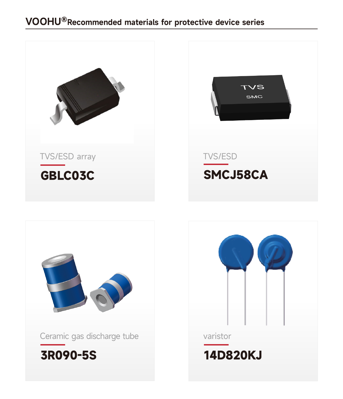
Circuit Functional Description
• BOB Smith Circuit: This circuit, consisting of a 75Ω resistor and a 1nF capacitor, provides a return path for common-mode signals, effectively filtering out common-mode signals, improving electromagnetic interference (EMI), and somewhat suppressing inrush current.
• Decoupling Capacitor: A 100nF capacitor is used to filter high-frequency noise and ensure signal stability and integrity.
• Withstand Voltage Capacitor: The 1nF capacitor must have a withstand voltage of 2kV or higher to ensure reliability in high-voltage environments.
This solution is designed for outdoor POE network port surge protection. It utilizes secondary protection, ensuring stable and reliable signal integrity over high temperatures. It meets the IEC61000-4-2 standard, Class 4, with a contact discharge rating of 30kV and an air discharge rating of 30kV. IEC61000-4-5 10/700us 40 6KV ±5 times, no packet loss in high temperature transmission.
Product images--Recommended products
 Direct product links:
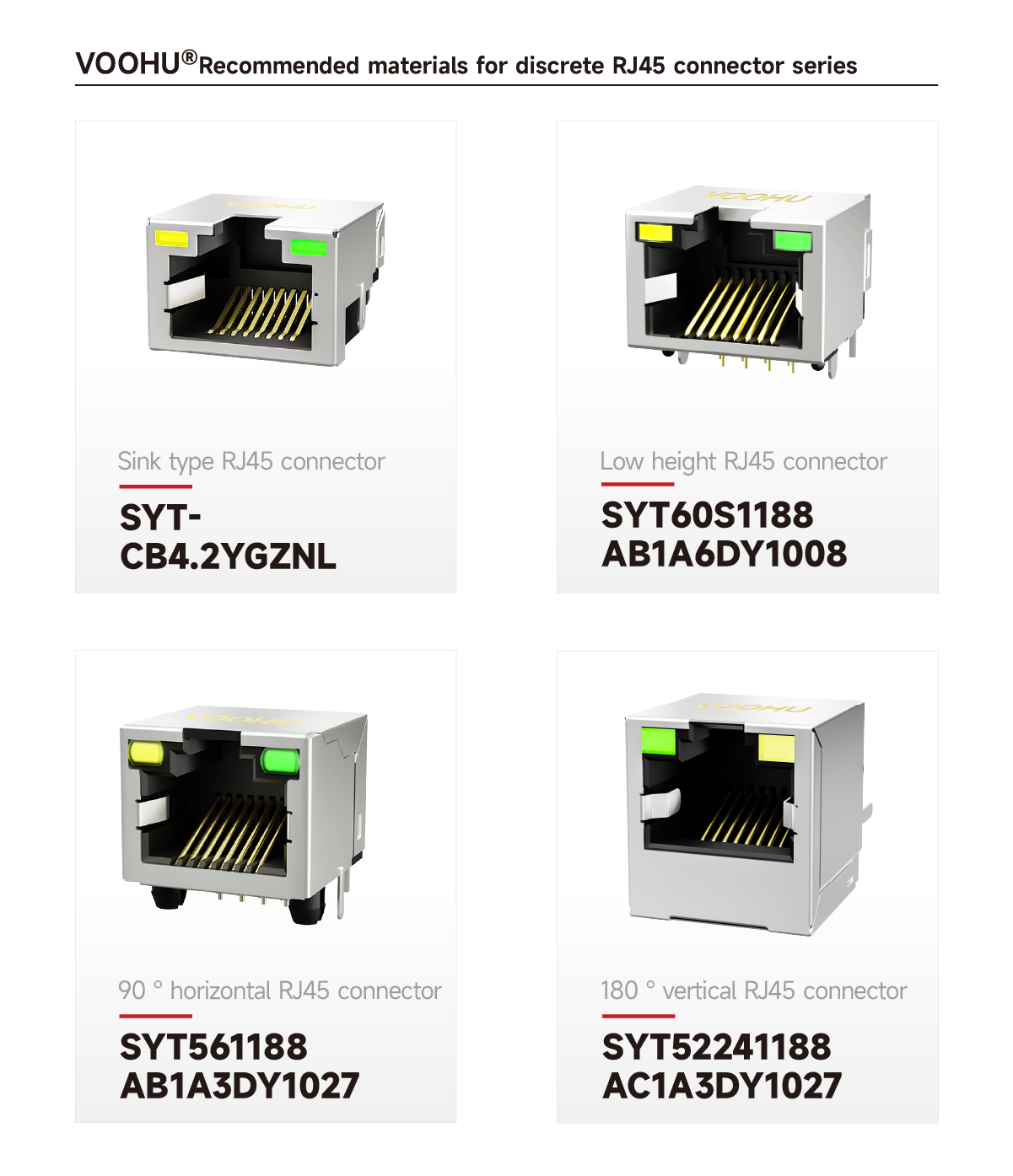
SYT-CB4.2YGZNL, SYT60S1188AB1A6DY1008 (curved leads), SYT561188AB1A3DY1027, SYT52241188AC1A3DY1027

Direct product links:
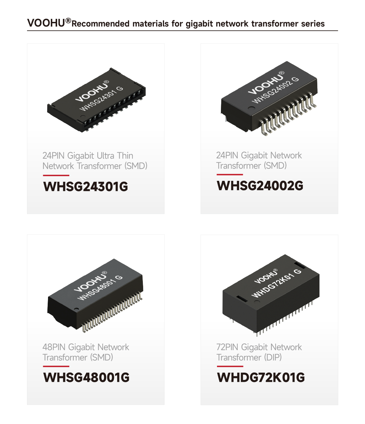
WHSG24301G, WHSG24002G, WHSG48001G, WHDG72K01G

POE Outdoor Lightning Protection 6KV Solution (Solution 1)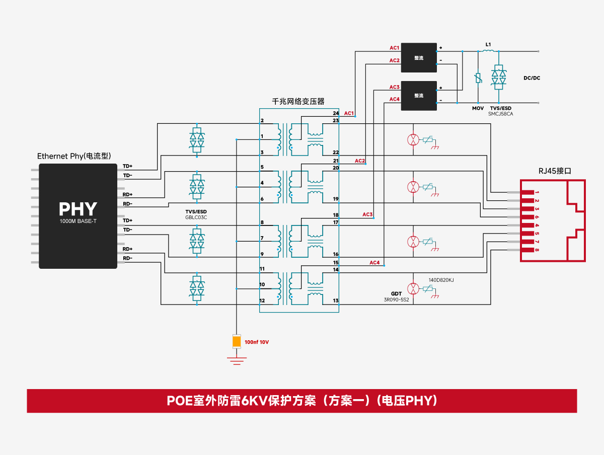
1. Primary Side Wiring:
• Differential Pair Connection: Connect the TD0/TD1 and RD0/RD1 differential pairs to the primary side of the network transformer. The wiring order of the four differential pairs can be swapped during PCB layout.
• Decoupling Capacitor: The primary side should be connected to GND via a 100nF capacitor to ensure signal stability and integrity.
2. Secondary Side Wiring:
• RJ45 Connection: Connect the two sets of transmit and receive differential signals on the secondary side to pins 1, 2, 3, 6 and 4, 5, 7, 8 of the RJ45 connector, respectively.
• Bob Smith Circuit: Connect each 75Ω resistor to the secondary side, then to chassis ground via a 1nF capacitor with a withstand voltage of 2kV or higher. 1206 packaged surface-mount ceramic capacitors or high-voltage ceramic capacitors with a wider pitch are recommended.
3. Grounding:
• Floating Pins: The floating pins of the RJ45 connector should also be connected to the chassis ground using a similar design, ultimately flowing to the earth to ensure a complete grounding system for the entire circuit.
Circuit Functional Description
• BOB Smith Circuit: This circuit, consisting of a 75Ω resistor and a 1nF capacitor, provides a return path for common-mode signals, effectively filtering out common-mode signals, improving electromagnetic interference (EMI), and somewhat suppressing inrush current.
• Decoupling Capacitor: A 100nF capacitor is used to filter high-frequency noise and ensure signal stability and integrity.
• Withstand Voltage Capacitor: The 1nF capacitor must have a withstand voltage of 2kV or higher to ensure reliability in high-voltage environments.
For outdoor POE port surge protection, this solution utilizes secondary protection, ensuring reliable operation and signal integrity at high temperatures. It meets IEC61000-4-2, Level 4, with a contact discharge rating of 30kV and an air discharge rating of 30kV.
IEC61000-4-510/700us, 400, 4kV, 5 times, LMBJ58CP4 is designed for POE 48V power supply. This solution can transmit at high temperature without packet loss.
Product images--Recommended products
Direct product links:
SYT-CB4.2YGZNL, SYT60S1188AB1A6DY1008 (curved leads), SYT561188AB1A3DY1027, SYT52241188AC1A3DY1027
Direct product links:
WHSG24301G, WHSG24002G, WHSG48001G, WHDG72K01G
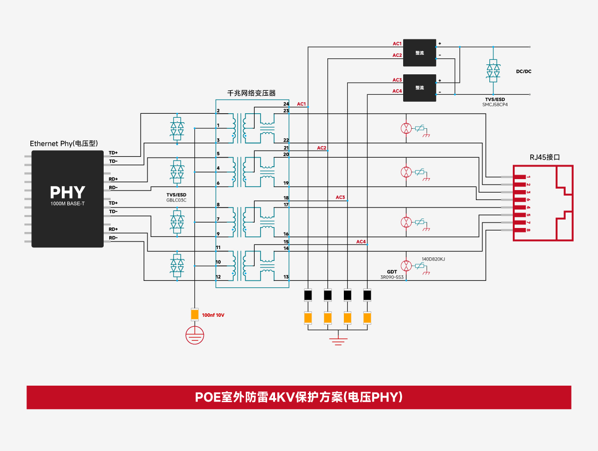
POE outdoor lightning protection 4KV protection solution (voltage type)
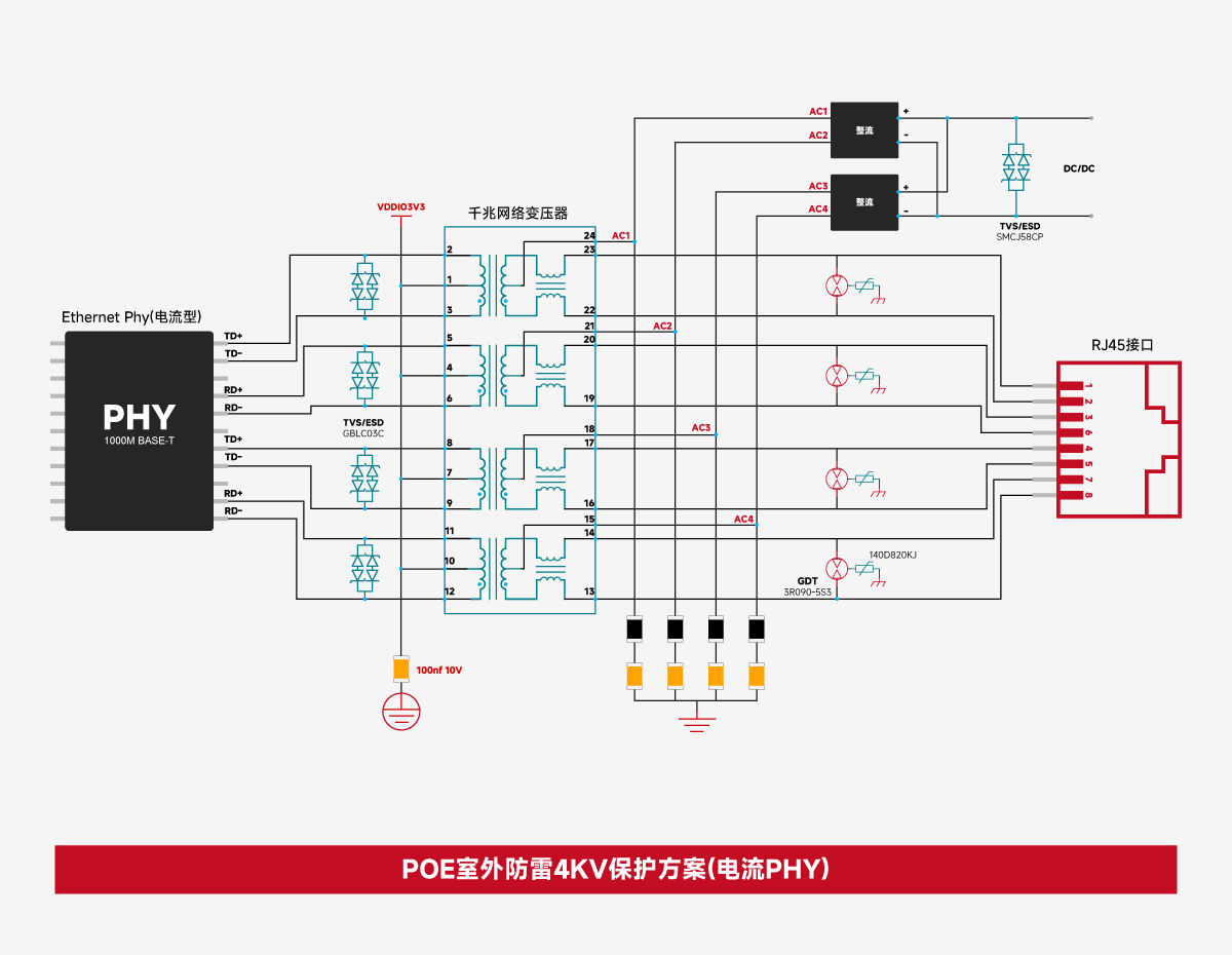
POE outdoor lightning protection 4KV protection solution (current type)
Note: The above scheme is a standard design and is for reference only. The final circuit design will be adjusted based on site requirements. Please call us for free in-depth support.
Tel: 400-1048-018; Email: wohu@wohu-tek.com;
From its founding in 2018 to its international expansion in 2025, Voohu Electronics has become a reliable partner to over 1,000 businesses thanks to its commitment to quality, competitive pricing, attentive service, and reliable delivery.
If you're looking for a hassle-free, cost-effective, and hassle-free supplier of communications electronic components, Voohu is a good choice. After all, a choice from over 100 publicly listed companies is a surefire way to go.
"Choose Voohu, Truly Reliable" isn't just a slogan; it's the answer, proven by the trust of over 1,000 customers over the past eight years.
This solution is a standard outdoor POE network port surge protection solution from VOOHU Electronic Technology (VOOHU). VOOHU has specialized in communications electronic components for over eight years. Adhering to the business strategy and service philosophy of "Choose VOOHU for Truly Reliable," VOOHU provides comprehensive technical support.
6KV Outdoor POE Lightning Protection Solution
Solution Overview
1. Primary Side Wiring:
• Differential Pair Connection: Connect the TD0/TD1 and RD0/RD1 differential pairs to the primary side of the network transformer. The wiring order of the four differential pairs can be swapped during PCB layout.
• Decoupling Capacitor: Connect the primary side to GND via a 100nF capacitor to ensure signal stability and integrity.
• VCC Power Supply: For current-mode PHYs, the primary coil needs to be connected to the PHY's VCC to filter high-frequency noise and ensure signal stability.
2. Secondary Side Wiring:
• RJ45 Connection: Connect the two sets of transmit and receive differential signals on the secondary side to pins 1, 2, 3, 6 and 4, 5, 7, 8 of the RJ45 connector, respectively.
• BOB Smith Circuit: Connect each secondary side to a 75Ω resistor, then to chassis ground via a 1nF capacitor with a voltage rating of 2kV or higher. 1206 packaged surface-mount ceramic capacitors or high-voltage ceramic capacitors with a wider pitch are recommended.
3. Grounding:
• Floating Pin: The floating pin of the RJ45 connector should also be connected to the chassis ground using a similar design, ultimately flowing to the earth to ensure a complete grounding system for the entire circuit.
Circuit Functional Description
• BOB Smith Circuit: This circuit, consisting of a 75Ω resistor and a 1nF capacitor, provides a return path for common-mode signals, effectively filtering out common-mode signals, improving electromagnetic interference (EMI), and somewhat suppressing inrush current.
• Decoupling Capacitor: A 100nF capacitor is used to filter high-frequency noise and ensure signal stability and integrity.
• Withstand Voltage Capacitor: The 1nF capacitor must have a withstand voltage of 2kV or higher to ensure reliability in high-voltage environments.
This solution is designed for outdoor POE network port surge protection. It utilizes secondary protection, ensuring stable and reliable signal integrity over high temperatures. It meets the IEC61000-4-2 standard, Class 4, with a contact discharge rating of 30kV and an air discharge rating of 30kV. IEC61000-4-5 10/700us 40 6KV ±5 times, no packet loss in high temperature transmission.
Product images--Recommended products
Direct product links:SYT-CB4.2YGZNL, SYT60S1188AB1A6DY1008 (curved leads), SYT561188AB1A3DY1027, SYT52241188AC1A3DY1027
Direct product links:
WHSG24301G, WHSG24002G, WHSG48001G, WHDG72K01G
POE Outdoor Lightning Protection 6KV Solution (Solution 1)
- Current-Type PHY Standard Design Reference - POE Outdoor 6KV Lightning Protection Solution (Scheme 2)

POE Outdoor Lightning Protection 4KV Solution
Solution Overview
1. Primary Side Wiring:
• Differential Pair Connection: Connect the TD0/TD1 and RD0/RD1 differential pairs to the primary side of the network transformer. The wiring order of the four differential pairs can be swapped during PCB layout.
• Decoupling Capacitor: The primary side should be connected to GND via a 100nF capacitor to ensure signal stability and integrity.
2. Secondary Side Wiring:
• RJ45 Connection: Connect the two sets of transmit and receive differential signals on the secondary side to pins 1, 2, 3, 6 and 4, 5, 7, 8 of the RJ45 connector, respectively.
• Bob Smith Circuit: Connect each 75Ω resistor to the secondary side, then to chassis ground via a 1nF capacitor with a withstand voltage of 2kV or higher. 1206 packaged surface-mount ceramic capacitors or high-voltage ceramic capacitors with a wider pitch are recommended.
3. Grounding:
• Floating Pins: The floating pins of the RJ45 connector should also be connected to the chassis ground using a similar design, ultimately flowing to the earth to ensure a complete grounding system for the entire circuit.
Circuit Functional Description
• BOB Smith Circuit: This circuit, consisting of a 75Ω resistor and a 1nF capacitor, provides a return path for common-mode signals, effectively filtering out common-mode signals, improving electromagnetic interference (EMI), and somewhat suppressing inrush current.
• Decoupling Capacitor: A 100nF capacitor is used to filter high-frequency noise and ensure signal stability and integrity.
• Withstand Voltage Capacitor: The 1nF capacitor must have a withstand voltage of 2kV or higher to ensure reliability in high-voltage environments.
For outdoor POE port surge protection, this solution utilizes secondary protection, ensuring reliable operation and signal integrity at high temperatures. It meets IEC61000-4-2, Level 4, with a contact discharge rating of 30kV and an air discharge rating of 30kV.
IEC61000-4-510/700us, 400, 4kV, 5 times, LMBJ58CP4 is designed for POE 48V power supply. This solution can transmit at high temperature without packet loss.
Product images--Recommended products
Direct product links:
SYT-CB4.2YGZNL, SYT60S1188AB1A6DY1008 (curved leads), SYT561188AB1A3DY1027, SYT52241188AC1A3DY1027
Direct product links:
WHSG24301G, WHSG24002G, WHSG48001G, WHDG72K01G
POE outdoor lightning protection 4KV protection solution (voltage type)
POE outdoor lightning protection 4KV protection solution (current type)
Note: The above scheme is a standard design and is for reference only. The final circuit design will be adjusted based on site requirements. Please call us for free in-depth support.
Tel: 400-1048-018; Email: wohu@wohu-tek.com;
From its founding in 2018 to its international expansion in 2025, Voohu Electronics has become a reliable partner to over 1,000 businesses thanks to its commitment to quality, competitive pricing, attentive service, and reliable delivery.
If you're looking for a hassle-free, cost-effective, and hassle-free supplier of communications electronic components, Voohu is a good choice. After all, a choice from over 100 publicly listed companies is a surefire way to go.
"Choose Voohu, Truly Reliable" isn't just a slogan; it's the answer, proven by the trust of over 1,000 customers over the past eight years.
share to
Related links
Newsletter subscription
Subscribe to our newsletter and stay updated on the latest information of our company and product.
Name
|
Subscribe
I agree that the information that I provide will be used in accordance with the terms of Voohu International Inc. Privacy & Cookies Policy


