


A Few Things About SFP Cage and Its Accessories
1. SFP CAGE family
-
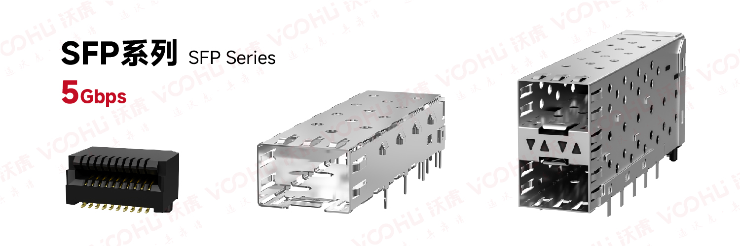
- ① SFP Series
·Supports data rates up to 5Gbps
·20-bit PT (pluggable transceiver) connector
·Single-port, multi-port and stacked cages available
·Standard and low-profile options for stacked ports
·EMI shrapnel or light guide options
-
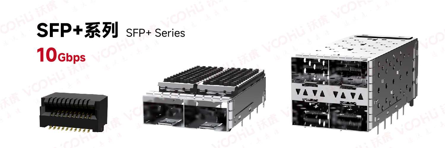
- ② SFP+ Series
• Supports data rates up to 10 Gbps
• 20-position PT connector
• EMI springs or gaskets, light guides and heat sink options
• Connectors and cable assemblies are backward compatible with SFP
-
-
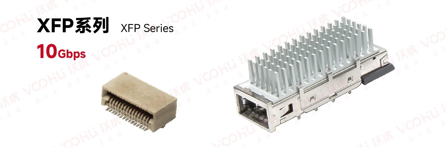
- ③ XFP Series
• Supports up to 10G bps SONET/SDH
• 30-bit SMT connector
• EMI shrapnel or gasket, heat sink options
• Designed for long-distance transmission, supports up to 100KM transmission
- ③ XFP Series
-
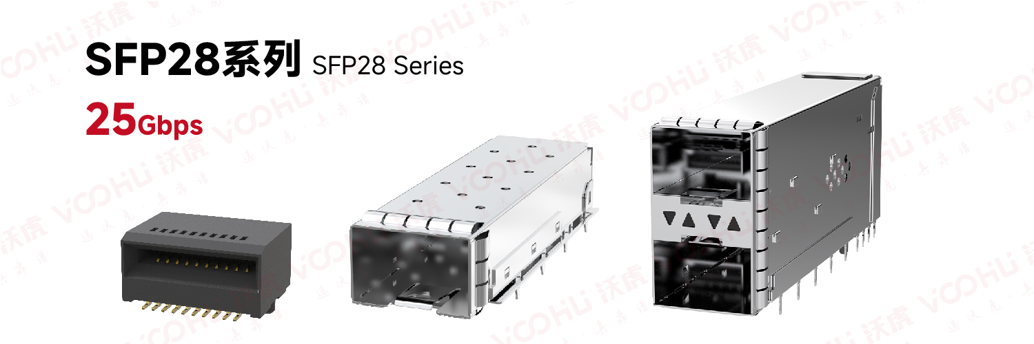
- ④SFP28 Series
• Supports data rates up to 25Gbps NRZ and 50Gbps PAM4
• 20-bit PT connector
• EMI shrapnel or gasket, light guide and heat sink options
• Connector and 1xN cage backward compatible with SFP+
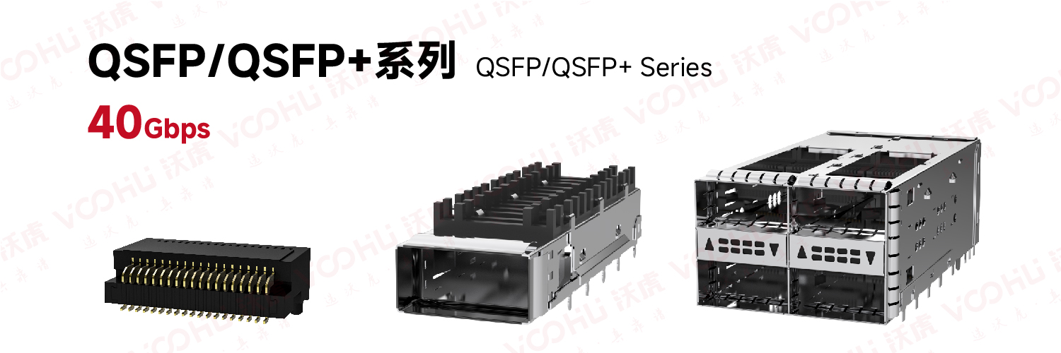
- ⑤QSFP/QSFP+ Series
• Supports data rates up to 40 Gbps, 10 Gbps per channel
• Four-channel package, 3 times the density of traditional SFP ports
• 38-position SMT connector
• Available in through-type and back-panel cage options
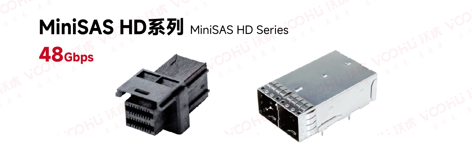
- ⑥MiniSAS HD Series
• Compliant with SFF-8644 and SAS 2.1 / 3.0 standards
• Improved cable lock design
• Expandable 4x and 8x cable plug configurations
• 26, 28 and 30AWG bulk cables
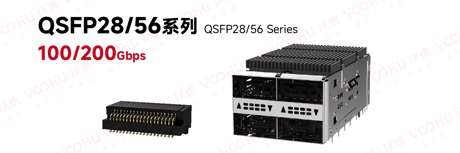
- ⑦QSFP28/56 Series
• Supports data rates over 100 Gbps, 28 Gbps per channel
• New connector design provides excellent signal integrity
• Press-fit pin layout supports Belly-to-Belly applications
• Shares the same mating interface as QSFP+ package
• Provides 1xN, 2xN, cage structure
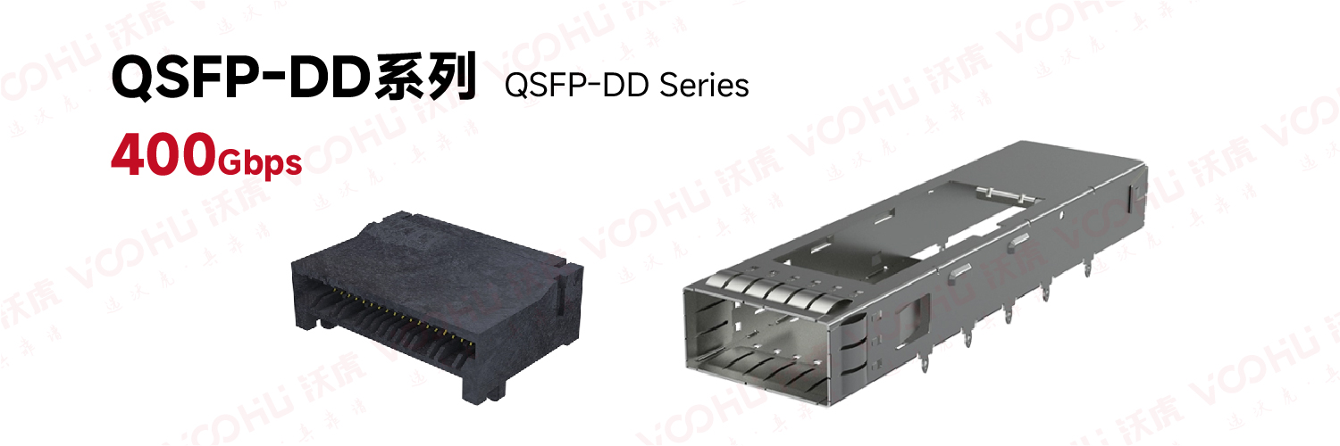
- ⑧QSFP-DD Series
• Same panel density as current 1xN QSFP28
• 1x1, 1x2, 1x3, 1x4, 1x5 and 1x6 cage structures available
• Cage structure compatible with Belly-to-Belly structure
• Connector adopts traditional 4-row SMT structure
• 56G QSFP-DD cage structure is directly compatible with QSFP-DD 112G connector
• Multiple heat sink and light pipe options available
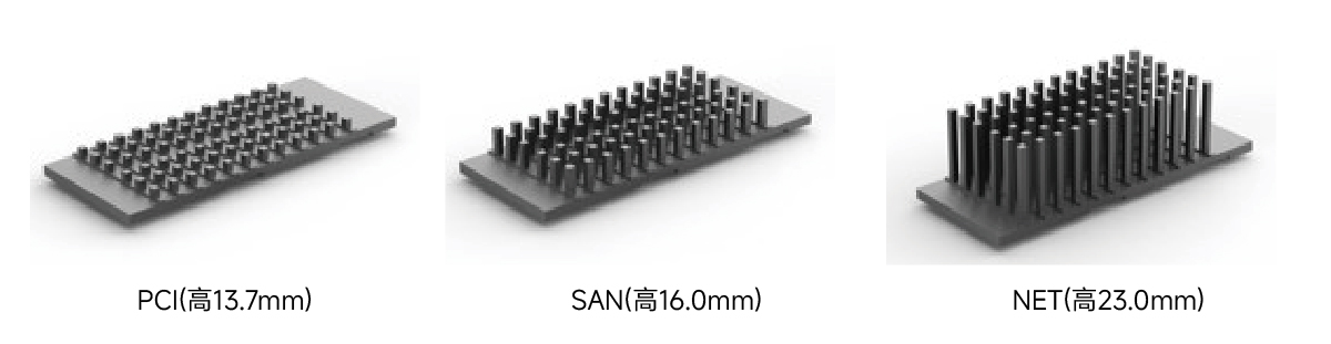
• Highly customizable based on standard PCIe, SAN and NET heat sinks, or customized according to customer needs
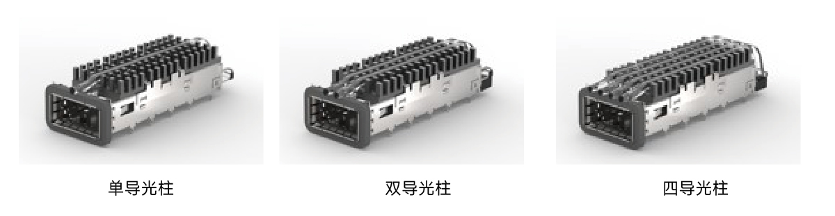
• 1, 2 and 4 light pipe configurations available
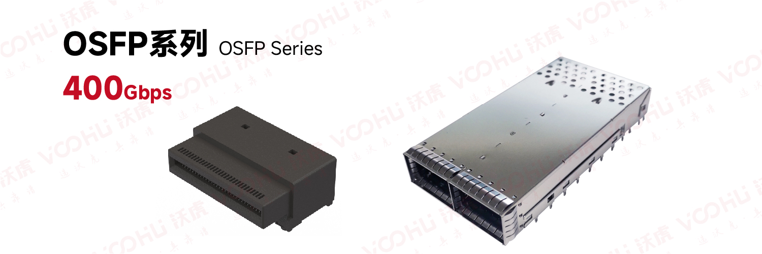
- ⑨OSFP Series
• Supports data rates up to 800 Gbps
• Excellent heat dissipation and signal integrity
• High port density
- 2. Function and location of SFP light guide column
1. Core function and implementation principle of light guide column
Status indication light transmission:
The core function of the light guide column is to guide the light emitted by the LED indicator light welded on the device PCB board to the device panel or the outside of the interface through a physical transmission path to form a visible status indication (such as link connection status, data transmission activity, etc.)
Light transmission mechanism: Based on the principle of total internal reflection (TIR), the light is transmitted to the exit end with low loss after multiple reflections inside the light guide column. The entrance of the light guide column needs to be precisely matched with the LED light-emitting surface to maximize the light coupling efficiency (the ideal efficiency can reach more than 92%), and the exit end is scattering to achieve uniform light emission at a wide viewing angle.
Elastic contact protection design:
In order to solve the problem of extrusion damage caused by inconsistent height of PCB welding LED, the light guide column adopts a curved structure to form elastic contact with the LED lamp beads instead of rigid collision, so as to avoid LED failure due to mechanical stress.
Cooperating with the limiting convex column on the base, the displacement range of the light guide column is further constrained to ensure the stability of the elastic contact.
2. Light guide column structural design features
Modular integration and installation optimization:
The light guide column is quickly plugged and fixed through the positioning column and slot structure (such as the slot on the base and the positioning column of the light guide column), simplifying the assembly process. Some designs also introduce light guide seats (located between the transverse partitions) to enhance the end positioning.
Split design: The light guide column cover assembly (such as the VOOHU WHSFP series) is packaged separately from the SFP Cage body, allowing the cage to be crimped to the PCB first, and then the light guide column cover is installed to avoid assembly interference and support later maintenance.
Compatibility and morphological adaptability:
The light guide column can be designed as a cylindrical, square, conical or custom shape (such as an arrow, star) to meet the indication and identification requirements of different devices.
Corners need to be rounded (radius ≥ 0.5mm) to avoid light escaping at sharp angles.
Support back/side installation, adapt to PCB layout flexibility, and avoid signal lines.
3. Light guide column position
1. Single-port and multi-port light guide column installation and position
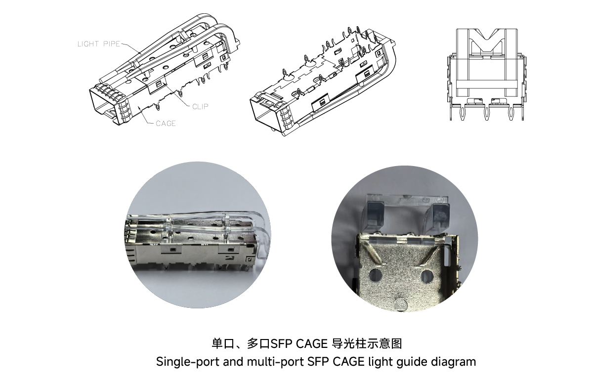
2. Stacked cage light guide column position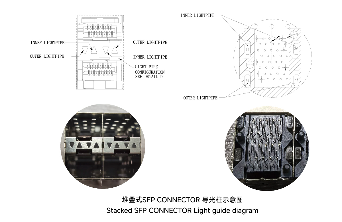
- 3. Specifications of optional products
1. 1xN mechanical options
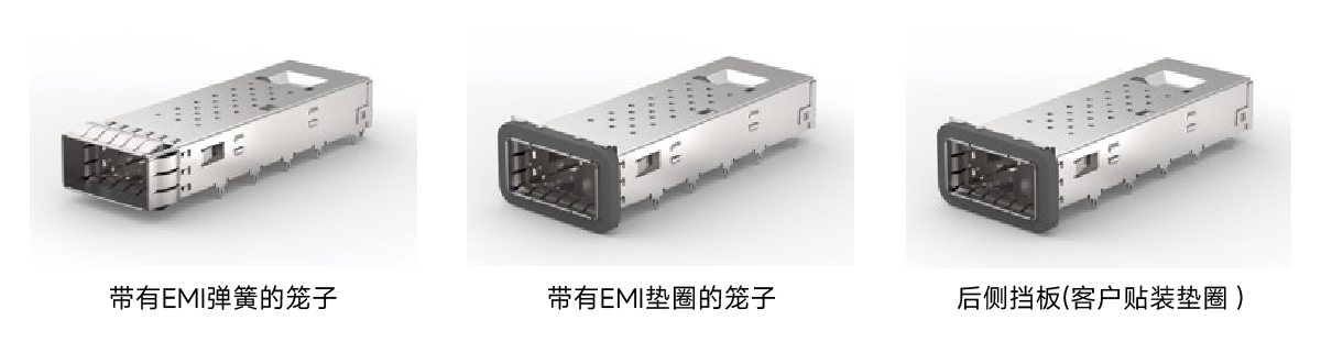
Baffle Mount Accessories
• Rear Baffle Cages use gaskets that are customer mounted on cage or baffle sheet metal
• EMI shrapnel and gasket type products use the same PCB footprint and baffle cutout
• VOOHU offers low insertion force EMI shrapnel to help assemble high density products
Radiator Accessories
• VOOHU provides SAN, LAN and Networking height radiators
• Customized radiators can be provided according to customer needs
• Height refers to the maximum height of the component measured from the PCB surface
Light guide accessories
• VOOHU provides 0, 1, 2 or 4 light guides for each port for customers to choose (2xN series light guides are 0, 2, 4 configurations)
• Standard light guides are designed to support LEDs with a maximum height of 1.00mm
• Light guides are shipped with a tray to prevent optical crosstalk
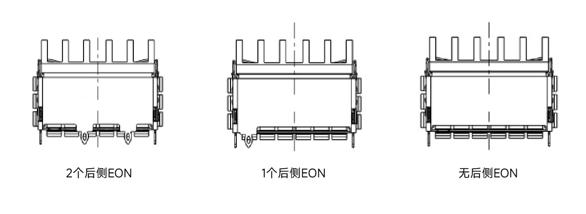
EON accessories
• The rear pins are used to improve the EMI grounding and the firmness of the cage connection to the PCB.
• The selection of the rear EON can be freely selected according to the customer's design
2. 2*N mechanical options
Baffle Mounting
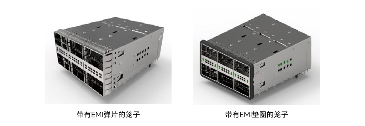
• Cage assemblies available with EMI shrapnel or EMI gaskets installed
• Custom gasket options available upon request
Light Guide Accessories
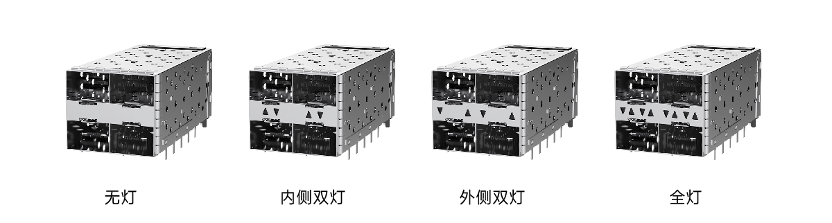
• VOOHU offers zero, single and dual light guide options for each port
• To increase the number of light guides, customers can add light guides below their PCB to indicate low-end port activity
• Thermal package design provides 4 light guides assembled above the cage
• Light guides are designed to support LEDs up to 0.80mm in height
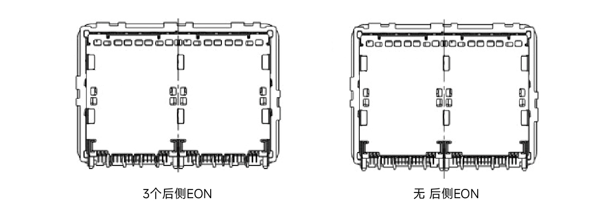
Rear EON
• Rear pins are used to improve EMI grounding and cage connection to PCB
• VOOHU provides zero or three rear pins for each port column
• Rear EON selection can be freely selected according to customer design
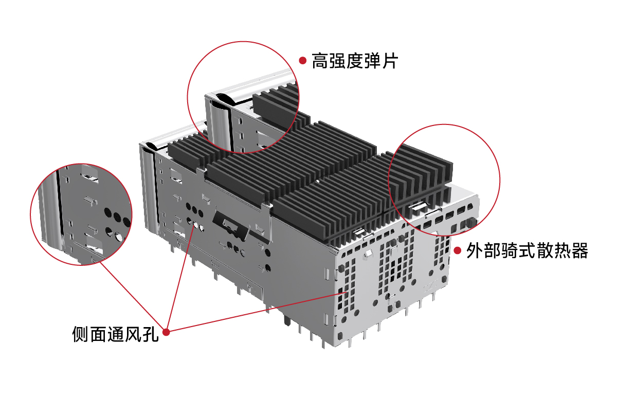
High Strength Springs - EMI Enhanced
• High performance springs are both flexible and strong.
• Improved springs provide a more complete seal to protect the connector from EMI
Heat Dissipation Enhancement
External Riding Heat Sink and Ventilation Optimization
External riding heat sink on top port optimized for airflow direction (also available without heat sink).
Vents allow air to flow and exit from the sides and back of the cage.
- 4. Shell material of SFPCAGE
The main material of SFP CAGE is generally nickel-nickel or stainless steel, with optional plating and thickness, usually nickel-plated 30μ”-50μ” or no nickel plating.
The advantages and disadvantages of stainless steel shell and nickel-nickel shell
Copper-nickel
Advantages: excellent conductivity (improves EMI shielding effect), good thermal conductivity (conducive to heat dissipation), high ductility (convenient for stamping).
Disadvantages: high cost, bare material is easy to oxidize in a humid environment, and nickel plating is required to avoid oxidation problems.
Stainless steel
Advantages: high mechanical strength, strong corrosion resistance (especially salt spray/humid heat environment), low cost.
Disadvantages: weaker conductivity and thermal conductivity than nickel-nickel, EMI shielding depends on plating supplement.
share to
Related links
Newsletter subscription
Subscribe to our newsletter and stay updated on the latest information of our company and product.
Name
|
Subscribe
I agree that the information that I provide will be used in accordance with the terms of Voohu International Inc. Privacy & Cookies Policy


