


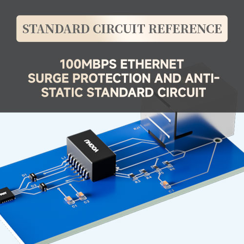
【Standard Circuit Design】 CHIP LAN Solution Standard Circuit Design Reference
This solution is a standard 100M Chip LAN circuit solution from VOOHU Electronic Technology. The company has been specializing in communications electronic components for over eight years. Adhering to the business strategy and service philosophy of "Choose VOOHU for Truly Reliable," VOOHU provides comprehensive technical solution support.
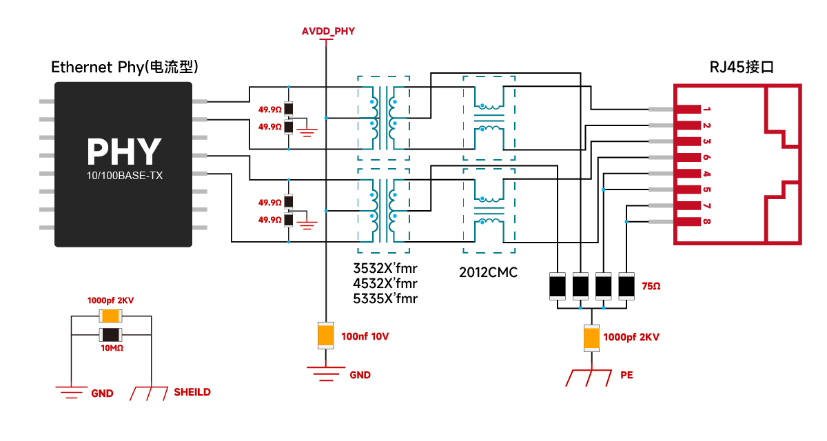
1. Primary Side Wiring:
Differential Pair Connection: Connect the TD and RD differential pairs to the primary side of the network transformer. The wiring order of the two differential pairs can be swapped during PCB layout.
Decoupling Capacitor: The primary side should be connected to GND via a 100nF capacitor to ensure signal stability and integrity.
VCC Power Supply: For current-mode PHYs, the primary coil needs to be connected to the PHY's VCC to filter high-frequency noise and ensure signal stability. It is recommended to connect two 49.9Ω resistors in parallel between each differential pair and connect them to GND.
2. Secondary Side Wiring:
RJ45 Connection: Connect the secondary side to pins 1, 2, 3, and 6 of the RJ45 connector.
BOB Smith Circuit: Connect a 75Ω resistor to the secondary side and the idle pins, then connect to the chassis ground via a 1nF capacitor with a voltage rating of 2kV or higher. 1206 packaged surface-mount ceramic capacitors or high-voltage ceramic capacitors with a wider pitch are recommended.
3. Grounding:
Floating Pins: The floating pins of the RJ45 connector should also be connected to the chassis ground using a similar design, ultimately flowing to the earth to ensure a complete grounding system for the entire circuit. Circuit Function Description
BOB Smith Circuit: This circuit, consisting of a 75Ω resistor and a 1nF capacitor, provides a return path for common-mode signals, effectively filtering out common-mode signals, improving electromagnetic interference (EMI), and somewhat suppressing inrush current.
Decoupling Capacitor: A 100nF capacitor is used to filter high-frequency noise and ensure signal stability and integrity.
High-Voltage Capacitor: The 1nF capacitor must have a voltage rating of 2kV or higher to ensure reliability in high-voltage environments.
10/100BASE-T network interface & Chip Lan (inductive) & voltage-type PHY circuit design
1. Primary Side Wiring:
Differential Pair Connection: Connect the TD and RD differential pairs to the primary side of the network transformer. The wiring order of the two differential pairs can be swapped during PCB layout.
Decoupling Capacitor: The primary side should be connected to GND via a 100nF capacitor to ensure signal stability and integrity.
2. Secondary Side Wiring:
RJ45 Connection: Connect the secondary side to pins 1, 2, 3, and 6 of the RJ45 connector.
BOB Smith Circuit: Connect a 75Ω resistor to the secondary side and the idle pin, then connect to chassis ground via a 1nF capacitor with a withstand voltage of 2kV or higher. 1206 packaged surface-mount ceramic capacitors or high-voltage ceramic capacitors with wide pitch are recommended.
3. Grounding:
Floating Pins: The floating pins of the RJ45 connector should also be connected to chassis ground using a similar design, ultimately to earth ground, to ensure a complete grounding system for the entire circuit. Circuit Function Description
BOB Smith Circuit: This circuit, consisting of a 75Ω resistor and a 1nF capacitor, provides a return path for common-mode signals, effectively filtering out common-mode signals, improving electromagnetic interference (EMI), and suppressing inrush current to a certain extent.
Decoupling Capacitor: This 100nF capacitor is used to filter out high-frequency noise and ensure signal stability and integrity.
High-voltage Capacitor: The 1nF capacitor must have a voltage rating of 2kV or higher to ensure reliability in high-voltage environments.
Advantages of this solution:
Chip Lan (inductive) transmits signals based on electromagnetic coupling, inheriting the mature and stable transmission characteristics of traditional grid transformers. Leveraging transformers, it provides high-voltage isolation, meeting electrical insulation requirements in high-voltage environments. Impedance matching is achieved through the transformer's turns ratio, a proven principle compatible with traditional grid transformers, facilitating system design and adaptation. Noise suppression utilizes center-tap or common-mode inductors, sharing the same noise suppression mechanism as traditional grid transformers and Chip Lan (capacitive) transformers. Its stable electromagnetic compatibility performance makes it particularly advantageous in scenarios requiring high-voltage isolation, while also ensuring reliable and adaptable signal transmission.
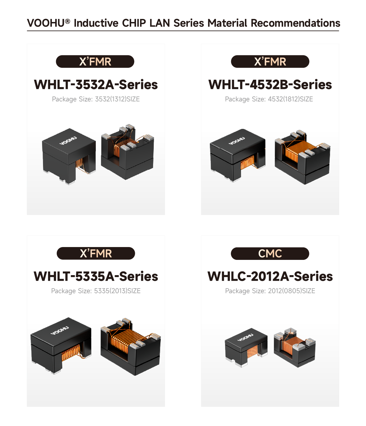
Product images--Recommended products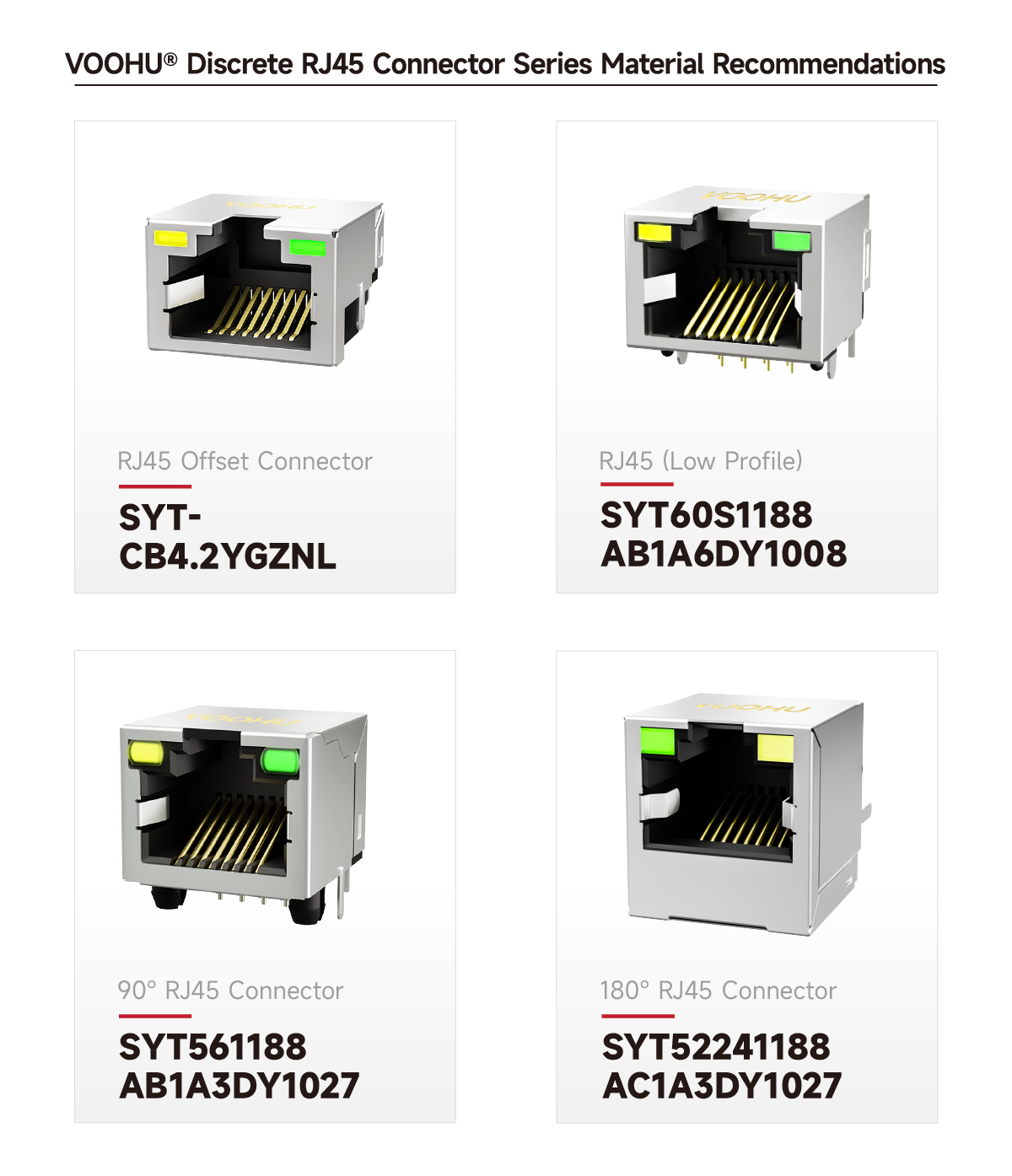
Chip Lan (inductive) & current-type PHY circuit design
Chip Lan (inductive) & voltage-based PHY circuit design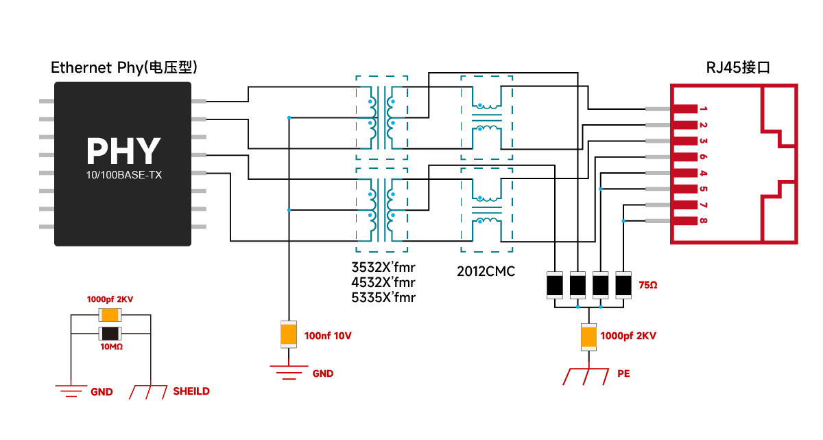
10/100BASE-T Network Interface & Chip Lan (Capacitor-Based) & Voltage-Based PHY Circuit Design
1. Primary Side Wiring:
Differential Pair Connection: Connect the TD and RD differential pairs to the primary side of the network transformer. The wiring order of the two differential pairs can be swapped during PCB layout.
Decoupling Capacitor: The primary side should be connected to GND via a 100nF capacitor to ensure signal stability and integrity.
2. Secondary Side Wiring:
RJ45 Connection: Connect the secondary side to pins 1, 2, 3, and 6 of the RJ45 connector.
BOB Smith Circuit: Connect the secondary side to a 75Ω resistor, then to chassis ground via a 1nF capacitor with a withstand voltage of 2kV or higher.
1206 packaged surface-mount ceramic capacitors or high-voltage ceramic capacitors with a wider pitch are recommended.
3. Grounding:
Floating Pins: The floating pins of the RJ45 connector should also be connected to the chassis ground using a similar design, ultimately flowing to the earth to ensure a complete grounding system for the entire circuit. Circuit Function Description.
BOB Smith Circuit: This circuit, consisting of a 75Ω resistor and a 1nF capacitor, provides a return path for common-mode signals, effectively filtering out common-mode signals, improving electromagnetic interference (EMI), and somewhat suppressing inrush current.
Decoupling Capacitor: A 100nF capacitor is used to filter high-frequency noise and ensure signal stability and integrity.
High-Voltage Capacitor: The 1nF capacitor must have a voltage rating of 2kV or higher to ensure reliability in high-voltage environments.
Advantages of this solution
Chip Lan (capacitive) transmits signals through capacitive DC isolation, accurately filtering DC interference to ensure effective transmission of pulse signals. Impedance matching is achieved through an equivalent circuit consisting of capacitors, common-mode inductors, and autotransformers, providing flexible adaptation to varying impedance requirements. Noise suppression relies on common-mode inductors or autotransformers, achieving the same noise suppression effect as Chip Lan (inductive) and traditional network transformers. Without the need for an additional transformer, the circuit design is simpler, making it suitable for scenarios where DC isolation and flexible impedance matching are crucial.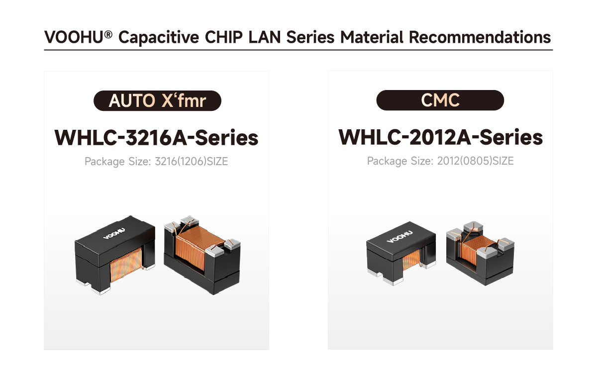
Chip Lan (capacitive) & voltage-based PHY circuit design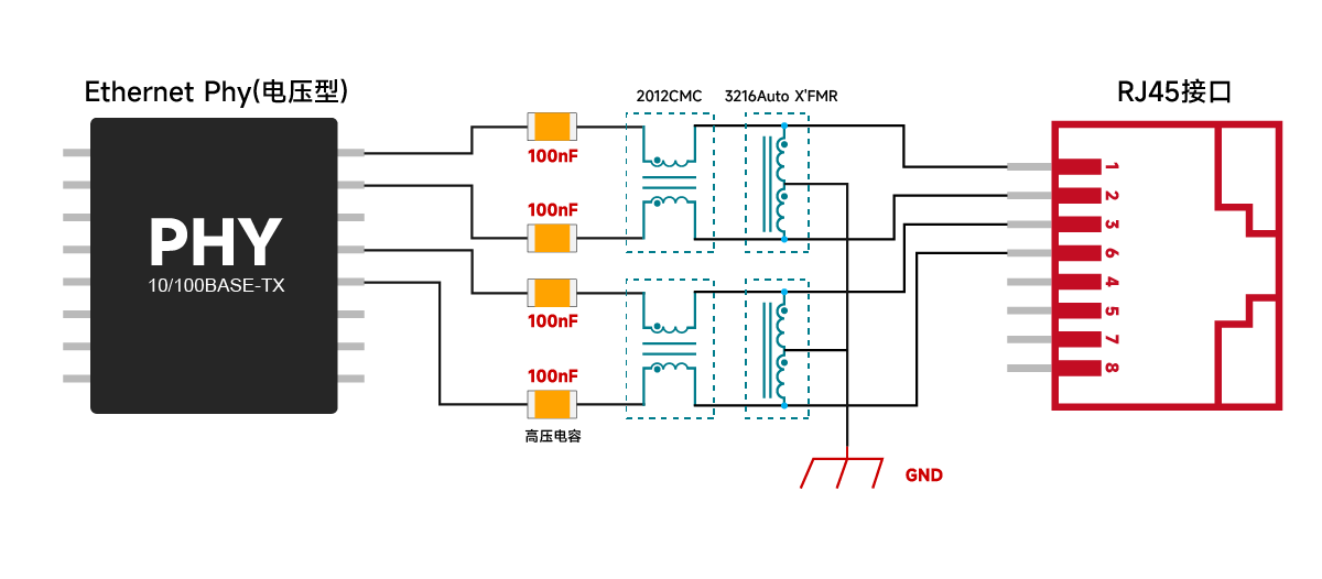
Note: The above solutions are standard designs for reference only. The final circuit design will be subject to on-site requirements. Please call us for free in-depth support.
Tel: 400-1048-018; Email: wohu@wohu-tek.com;
From its founding in 2018 to its international expansion in 2025, Voohu Electronics has become a reliable partner to over 1,000 businesses thanks to its commitment to quality, competitive pricing, attentive service, and reliable delivery.
If you're also looking for a hassle-free, cost-effective, and hassle-free supplier of communications electronic components, Voohu is a good choice. After all, the choice of over 100 publicly listed companies is a surefire way to go.
"Choose Voohu, Truly Reliable" isn't just a slogan; it's the answer, proven by the trust of over 1,000 customers over the past eight years.
Newsletter subscription
Subscribe to our newsletter and stay updated on the latest information of our company and product.
Name
|
I agree that the information that I provide will be used in accordance with the terms of Voohu International Inc. Privacy & Cookies Policy


