


Voltage-driven PHY vs. Current-driven PHY: How to correctly connect the network transformer?
Voltage-driven PHY vs. Current-driven PHY: How to correctly connect the network transformer?
In network communication equipment design, the connection method between the PHY chip and the lan transformer directly affects signal integrity, anti-interference capability, and overall system stability. As a FAE (Field Application Engineer) at Suzhou Voohu Electronics Technology Co., Ltd., we frequently encounter customer questions regarding PHY selection and transformer connection design. This article will analyze the differences in connection between voltage-driven and current-driven PHYs and lan transformers to help you avoid common pitfalls in your designs.
Current-driven PHY: Outputs a current signal, commonly found in early or some low-cost solutions.
Voltage-driven PHY: Outputs a voltage signal, currently widely used in Gigabit and higher Ethernet networks.
The different driving methods directly affect the connection and layout of peripheral circuits (especially the lan transformer).
II. Overview of Lan Transformer Structure
A Lan transformer typically includes:
Transformer (used for signal coupling and isolation)
Common-mode inductor (suppresses common-mode noise)
Center tap (provides bias or ground path)

Common structures include:
2-wire common-mode inductor + transformer
3-wire common mode inductor + transformer
III. Summary of Key Connection Rules
When designing connections, the following principles must be followed:
1. Common Mode Inductor Location
Current-driven PHY: The 2-wire common mode inductor must be placed on the cable (RJ45) side.
Voltage-driven PHY: The 2-wire common mode inductor can be placed on the PHY side or the cable side, offering greater flexibility.
3-wire Common Mode Inductor: Regardless of whether it's current-driven or voltage-driven, it should be placed on the PHY side.
2. Center Tap Connection
Current-driven PHY: The center tap is connected to the PHY supply voltage (VCC).
Voltage-driven PHY: The center tap is connected to the capacitor to ground.
3. Autotransformer Location
If using a "2-wire common mode inductor + autotransformer" structure, the autotransformer should be placed on the RJ45 side.
IV. Actual Chip Connection Examples
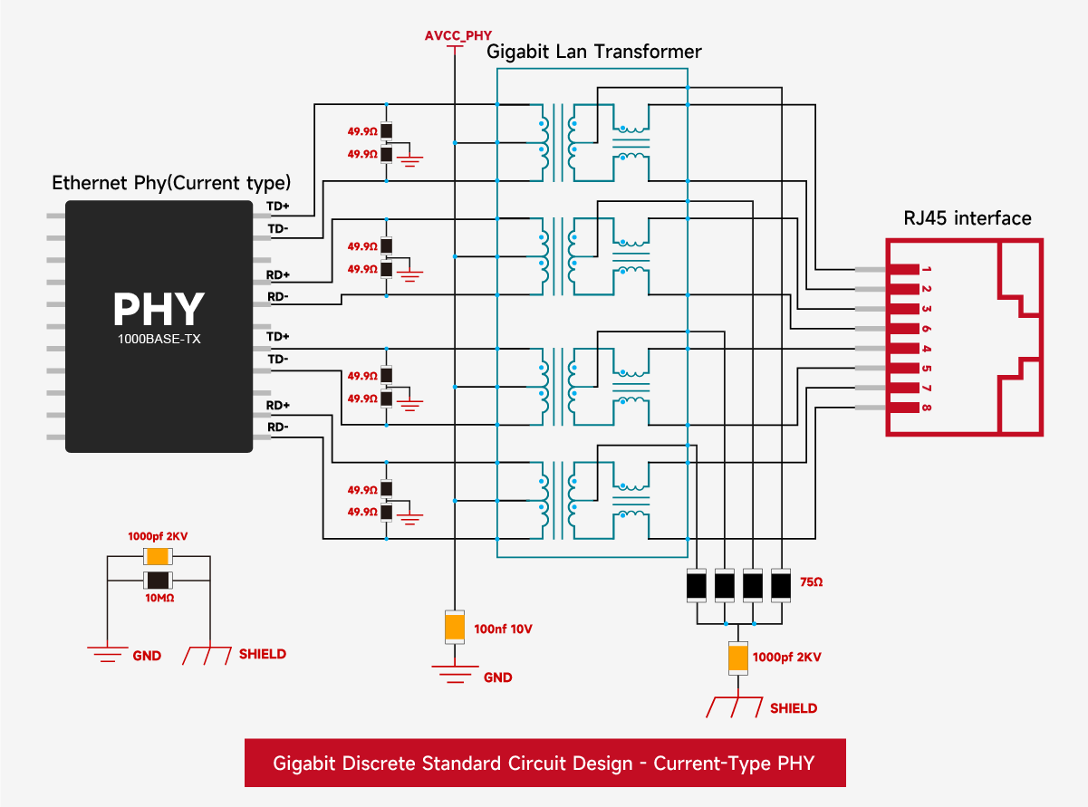
1. Current-driven type
Center tap connected to VDD
Common mode inductor close to the RJ45 side
Suitable for PoE scenarios, etc.
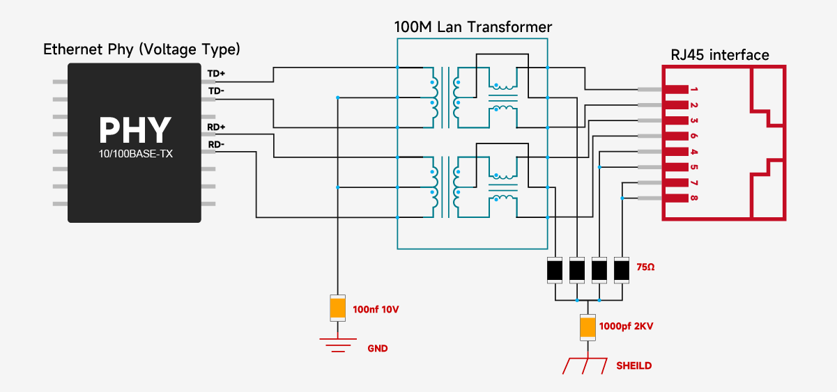
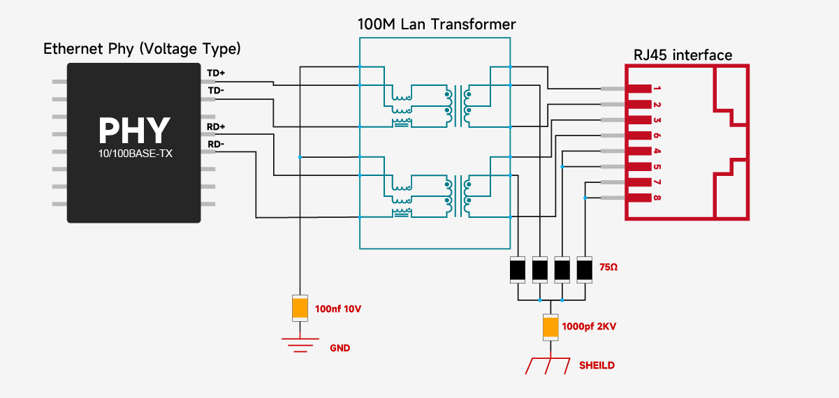
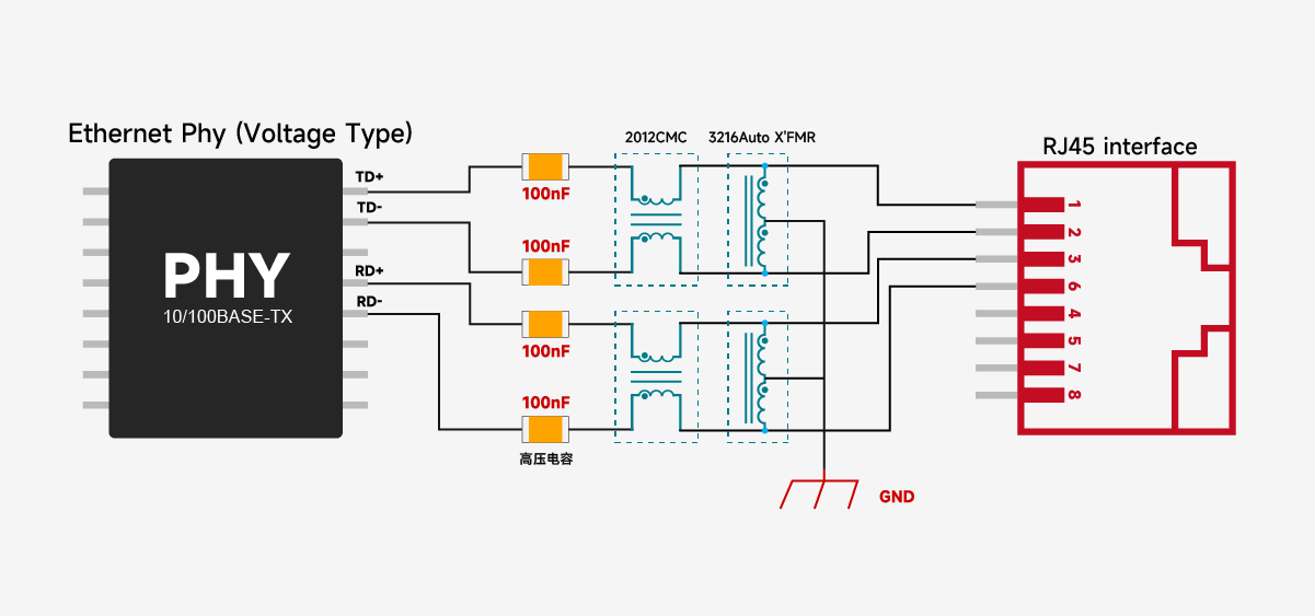
2. Voltage-driven type:
Center tap grounded via capacitor;
common-mode inductor can be located on the PHY side or MAC side;
commonly found in switch chips.

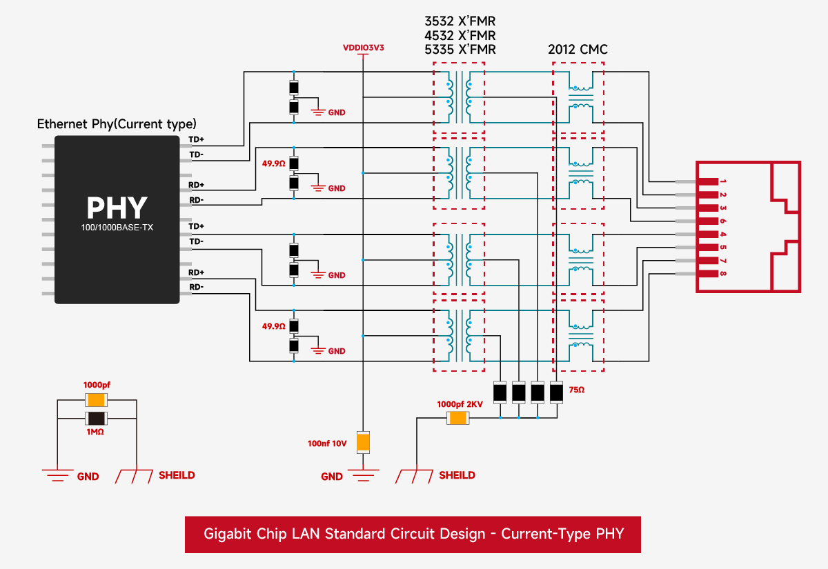
3. Current-driven type
All adopt a common-mode inductor-based RJ45 design
Support autotransformer structure
V. Design Recommendations and Common Misconceptions
Before selecting a PHY, be sure to confirm the PHY drive type and consult the "Magnetic Interface" section of the chip datasheet.
Current-driven PHYs are more sensitive to layout; the common-mode inductor position cannot be arbitrarily changed.
Voltage-driven PHYs offer more flexible layout, but it is still recommended to refer to the recommended circuit and optimize EMC performance.
Incorrect center tap connection may result in insufficient signal amplitude or excessive noise, affecting transmission distance and stability.
From its establishment in 2018 to its overseas expansion in 2025, Voohu Electronics has become a reliable partner for over 1000 companies thanks to its "superior quality, reasonable prices, attentive service, and reliable delivery."
If you are also looking for a "worry-free, cost-effective, and convenient" communication electronic component supplier, consider Voohu. After all, the choice of over 100 listed companies is unlikely to be wrong.
Choose Voohu – truly reliable. This is not just a slogan, but the answer written with the trust of over 1000 customers over 8 years.
I. Introduction to PHY Driving Methods
The PHY (Physical Layer Transceiver) is the core chip in Ethernet communication, responsible for signal modulation and demodulation. Based on its output driving method, it can be divided into:Current-driven PHY: Outputs a current signal, commonly found in early or some low-cost solutions.
Voltage-driven PHY: Outputs a voltage signal, currently widely used in Gigabit and higher Ethernet networks.
The different driving methods directly affect the connection and layout of peripheral circuits (especially the lan transformer).
II. Overview of Lan Transformer Structure
A Lan transformer typically includes:
Transformer (used for signal coupling and isolation)
Common-mode inductor (suppresses common-mode noise)
Center tap (provides bias or ground path)
Common structures include:
2-wire common-mode inductor + transformer
3-wire common mode inductor + transformer
- Autotransformer
III. Summary of Key Connection Rules
When designing connections, the following principles must be followed:
1. Common Mode Inductor Location
Current-driven PHY: The 2-wire common mode inductor must be placed on the cable (RJ45) side.
Voltage-driven PHY: The 2-wire common mode inductor can be placed on the PHY side or the cable side, offering greater flexibility.
3-wire Common Mode Inductor: Regardless of whether it's current-driven or voltage-driven, it should be placed on the PHY side.
2. Center Tap Connection
Current-driven PHY: The center tap is connected to the PHY supply voltage (VCC).
Voltage-driven PHY: The center tap is connected to the capacitor to ground.
3. Autotransformer Location
If using a "2-wire common mode inductor + autotransformer" structure, the autotransformer should be placed on the RJ45 side.
IV. Actual Chip Connection Examples
1. Current-driven type
Center tap connected to VDD
Common mode inductor close to the RJ45 side
Suitable for PoE scenarios, etc.
2. Voltage-driven type:
Center tap grounded via capacitor;
common-mode inductor can be located on the PHY side or MAC side;
commonly found in switch chips.
3. Current-driven type
All adopt a common-mode inductor-based RJ45 design
Support autotransformer structure
V. Design Recommendations and Common Misconceptions
Before selecting a PHY, be sure to confirm the PHY drive type and consult the "Magnetic Interface" section of the chip datasheet.
Current-driven PHYs are more sensitive to layout; the common-mode inductor position cannot be arbitrarily changed.
Voltage-driven PHYs offer more flexible layout, but it is still recommended to refer to the recommended circuit and optimize EMC performance.
Incorrect center tap connection may result in insufficient signal amplitude or excessive noise, affecting transmission distance and stability.
From its establishment in 2018 to its overseas expansion in 2025, Voohu Electronics has become a reliable partner for over 1000 companies thanks to its "superior quality, reasonable prices, attentive service, and reliable delivery."
If you are also looking for a "worry-free, cost-effective, and convenient" communication electronic component supplier, consider Voohu. After all, the choice of over 100 listed companies is unlikely to be wrong.
Choose Voohu – truly reliable. This is not just a slogan, but the answer written with the trust of over 1000 customers over 8 years.
share to
Related links
Newsletter subscription
Subscribe to our newsletter and stay updated on the latest information of our company and product.
Name
|
Subscribe
I agree that the information that I provide will be used in accordance with the terms of Voohu International Inc. Privacy & Cookies Policy


