


What you must know about SFP connectors
1. Function and material composition of SFP optical cage
1. Concept and function of optical cage
① What is optical cage?
SFP Cage (Small Form-factor Pluggable Cage) is the core mechanical and electrical interface component used to install and fix optical modules in communication equipment. It has a metal frame structure, which is composed of upper and lower covers and EMI shrapnel. It can add parts such as heat sink or light guide rod, and be crimped or welded on the equipment PCB (such as switch, router motherboard). It provides a physical slot for the optical module and realizes the connection between the optical module and the PCB board. Therefore, it is often called SFP optical cage or SFP connector.
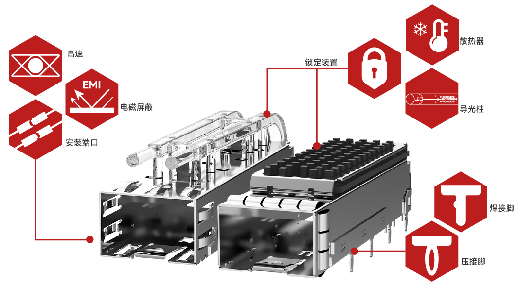
② What are the core functions of the optical cage?
1. Electrical connection and signal integrity
2. Electromagnetic shielding (EMI Suppression)
3. Mechanical fixation and module protection
4. Heat dissipation management and dust prevention
5. Other auxiliary functions: status indication and mis-insertion prevention with light guide
2. Product components and material composition of each part
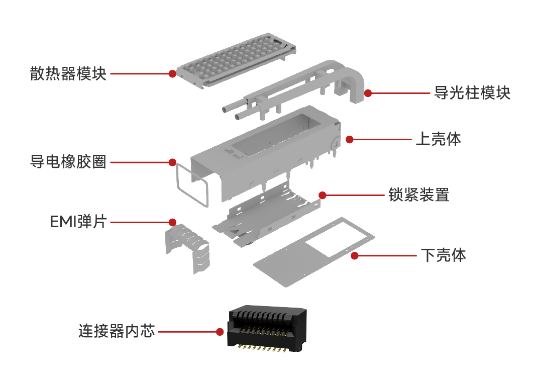
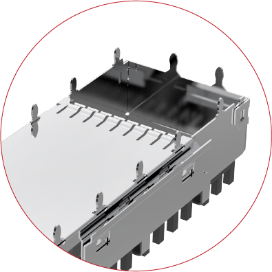
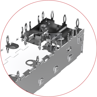
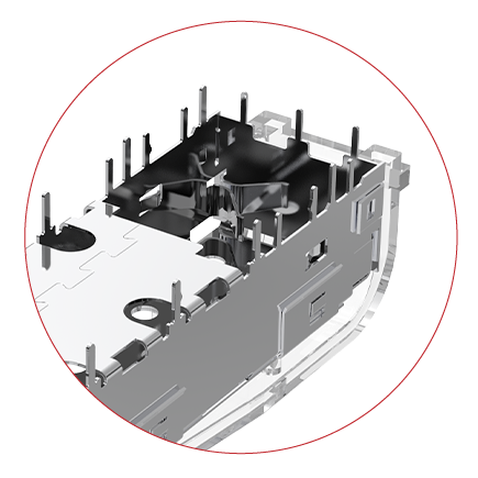
SFP optical cage is usually composed of a metal shielding shell and a connector core, and other accessories such as light guide, heat sink, etc. can be integrated according to needs.
Metal shielding shell:
It is composed of shielding shell + locking mechanism. Its main material is generally white copper or stainless steel. The plating and thickness are optional, usually nickel plating 30μ”-50μ” or no nickel plating.
Connector core:
It is composed of a base and signal terminal. The number of socket PIN is 20PIN. The processing method is surface mounting. It needs to be used with a single-layer optical cage when applied. The connector terminal is copper alloy or phosphor copper. The gold plating method is contact gold plating, and the gold plating thickness is optional.
Other accessories:
Light guide column - made of optical polycarbonate
Radiator - made of AL 6063
2. Product classification and selection of SFP optical cages
1. Product classification
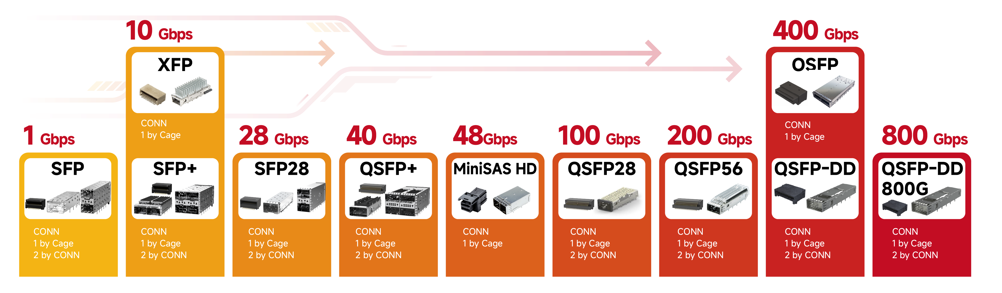
① Classification by speed
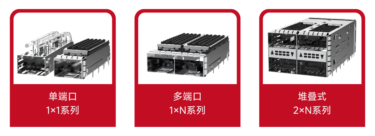
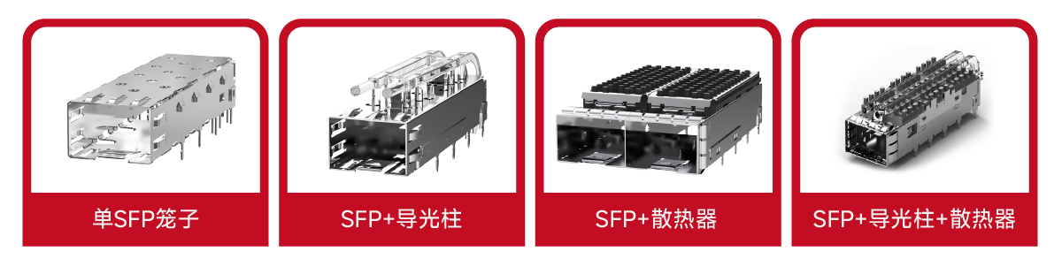
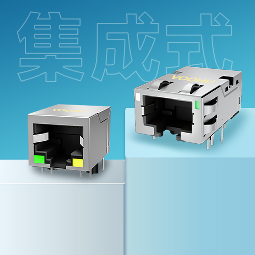
② Classification by product structure
③ Classification by product accessories
2. Selection Recommendations
Steps for SFP Cage Selection
1. Define Requirements
Determine the rate:
• Steps: Select a cage that supports 1G, 10G, 25G, 100G, 200G, 400G, 800G according to network requirements.
Determine the fiber type:
• Steps: Select a cage that supports single-mode or multi-mode fiber. If long-distance transmission is required, select a cage that supports single-mode fiber.
Determine the interface type:
• Steps: Select a cage with LC, SC, or FC interface.
2. Match the device
Check the device specifications:
• Steps: Make sure that the electrical and mechanical parameters of the cage are consistent with the device.
Reference compatibility list:
• Steps: Refer to the compatibility list of the device manufacturer to ensure that the cage is compatible with the device.
3. Evaluate the cost
Cage cost:
• Steps: Consider the unit price and bulk purchase cost of the cage.
Maintenance cost:
• Steps: Consider the reliability and maintenance cost of the cage.
Selection Guide for Special Scenarios
1. High-density cabling in data centers
High-density cages:
• Features: Support high-density cabling and reduce space occupancy.
• Recommendations: Select cages that support high-density cabling, such as QSFP cages.
Heat management:
• Features: High-power modules require good heat dissipation design.
• Recommendations: Select cages with heat sinks or heat pipes to ensure heat dissipation.
2. Harsh industrial environments
Reinforced design:
• Features: Corrosion-resistant, high-strength materials, such as stainless steel.
• Recommendations: Select cages made of stainless steel to ensure reliability in harsh environments.
Extended temperature range:
• Features: Supports a temperature range of -40℃ to +85℃.
• Recommendations: Select cages that support an extended temperature range to ensure stability in extreme environments.
3. Long-distance transmission
Support long-distance modules:
• Features: Modules that support long-distance transmission, such as 100km 10GBASE-ZR modules.
• Recommendation: Choose a cage that supports long-distance transmission to ensure signal quality.
Dispersion compensation:
• Features: Long-distance transmission requires a dispersion compensation module.
• Recommendation: Choose a cage that supports dispersion compensation to ensure signal quality for long-distance transmission.
III. Installation methods and fixtures
1. The difference between press-fit and soldering
Press-fit connection, as the name implies, is to press a pin with an interference size into a through hole drilled on the circuit board. The basic element is that the diameter of the pin's joint area must be larger than the hole diameter. This causes the material of the mating surface of the pin and the hole to deform, and the deformation of the pin or the through hole will also maintain the tight fit between the two.
Press-fit is divided into solid pin pins and fisheye pins (see the figure below for details)
1. Solid pin pins, the force that maintains good contact between the pin and the through hole is the elastic deformation force of the through hole.
2. Elastic deformation (fisheye pin EoN) The force that maintains good contact between the pin and the through hole is the elastic deformation force of the pin.
Compared with solid pins, elastic pins have lower requirements for the dimensional accuracy of PCB metallized through holes; smaller insertion force; and allow multiple plugging and unplugging in the metallized through holes of the same PCBA (good maintainability). Therefore, in the current PCBA processing crimping process, elastically deformable pins or fisheye pins are mainly used.
Welding connection, welding is a hot processing process, the pin is placed in the through hole, and the connection is achieved through molten solder.
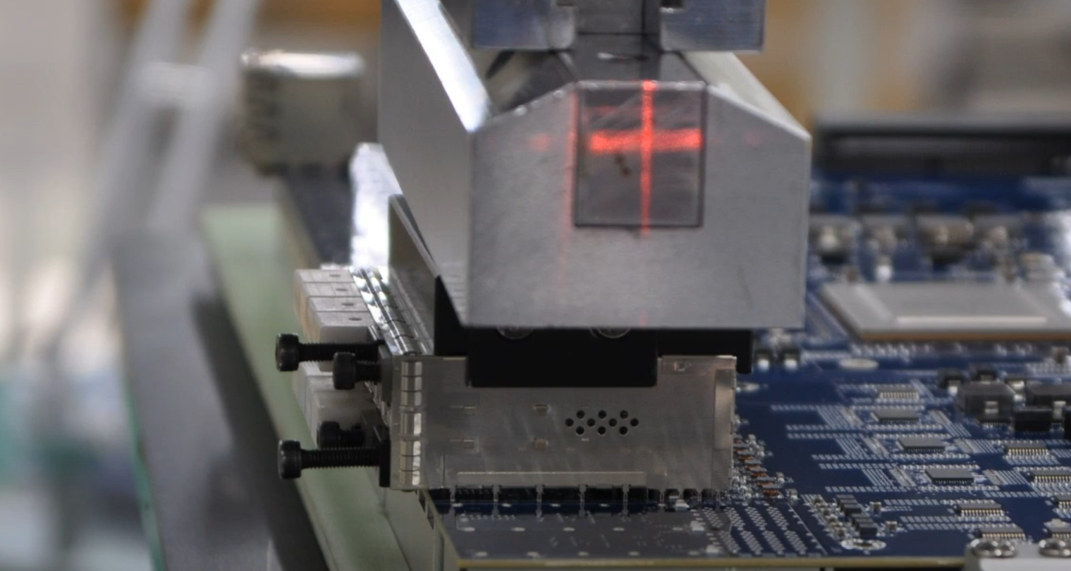
2. Press-fit installation steps
Installing a press-fit SFP optical cage requires the use of a dedicated press-fit machine and a press-fit fixture, using a three-stage press-in method for press-fitting.
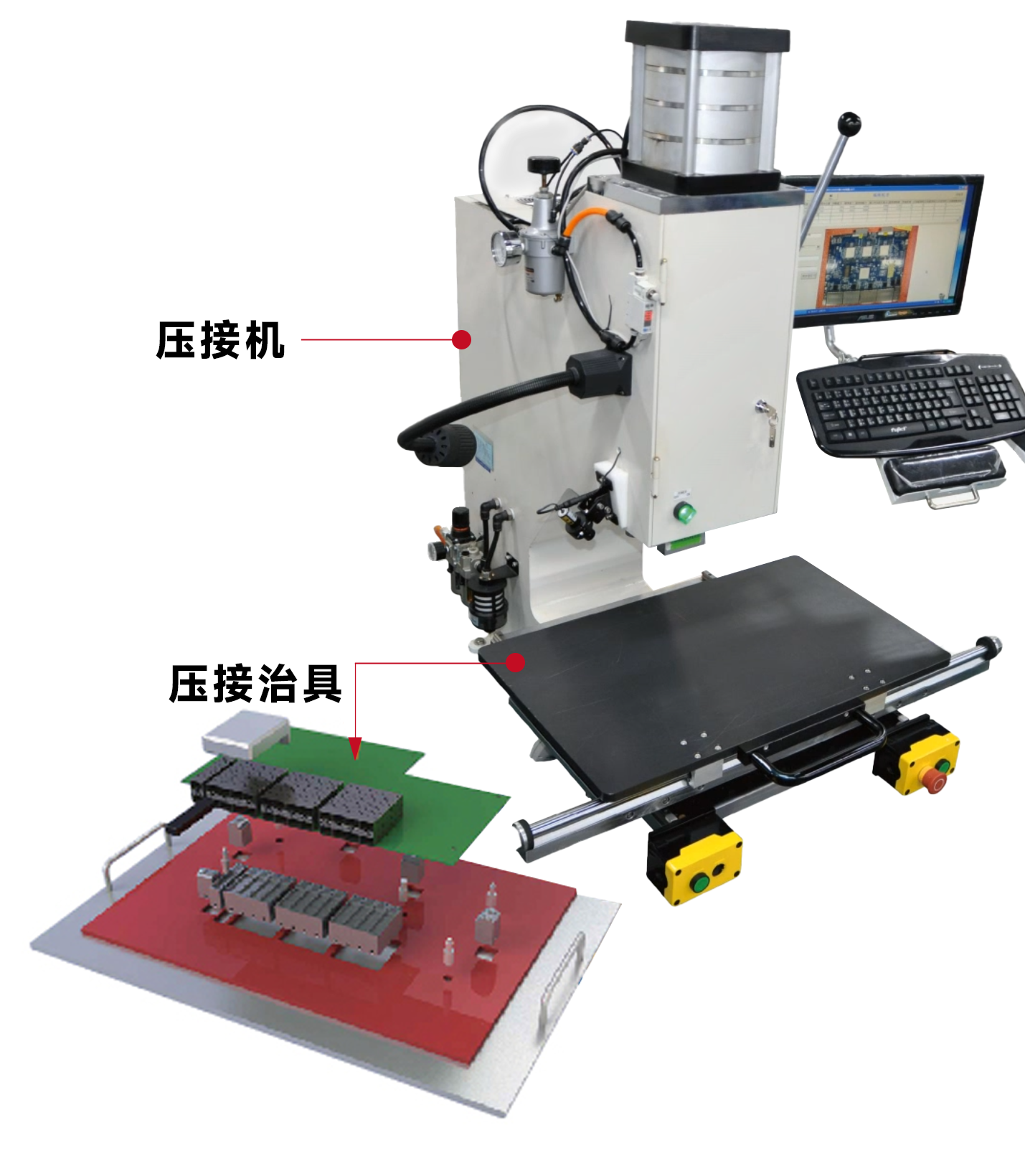
① Place the crimping jig flat on the crimping table
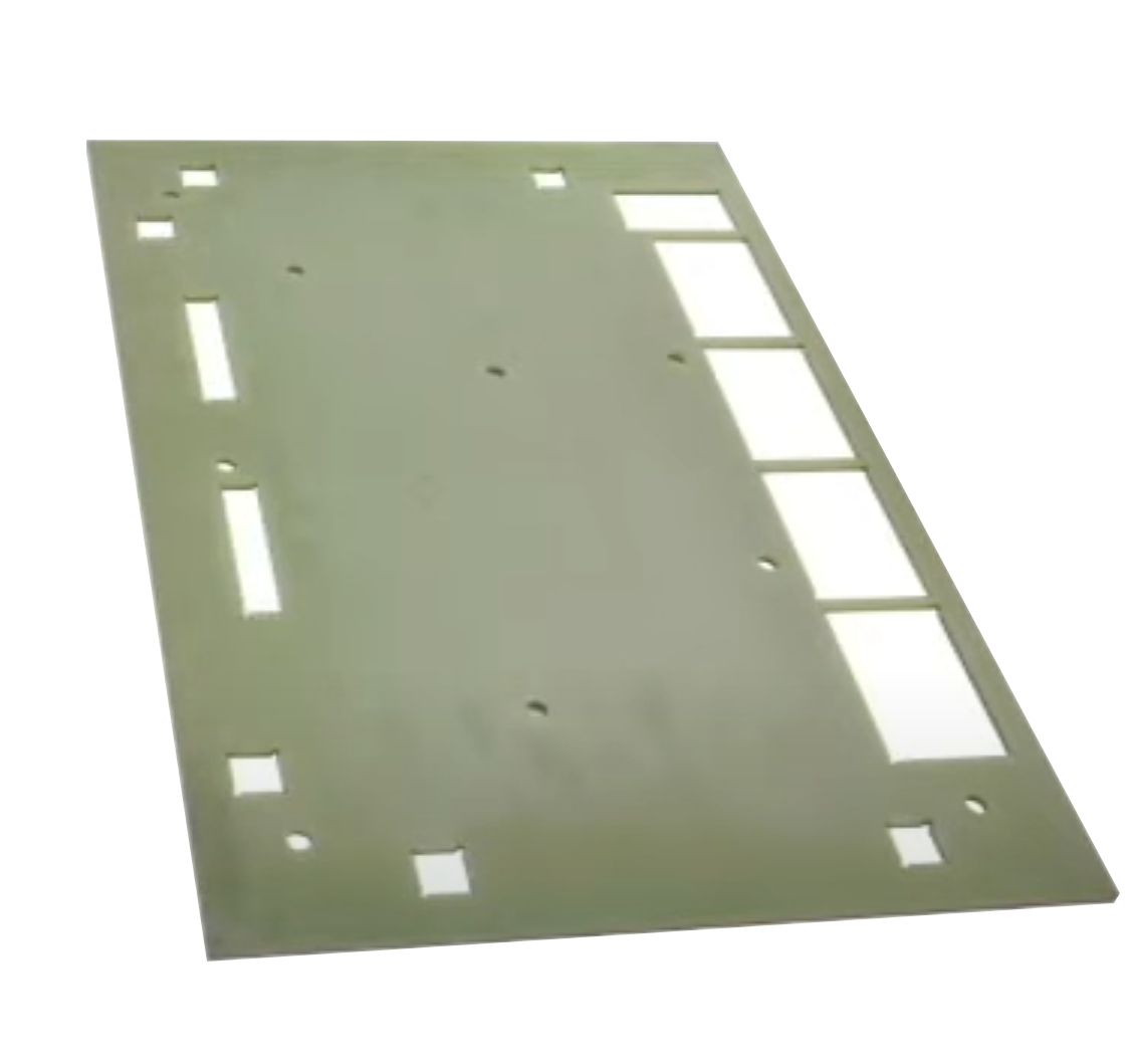
② Place the positioning block and SFP cage on the corresponding positions of the crimping fixture.
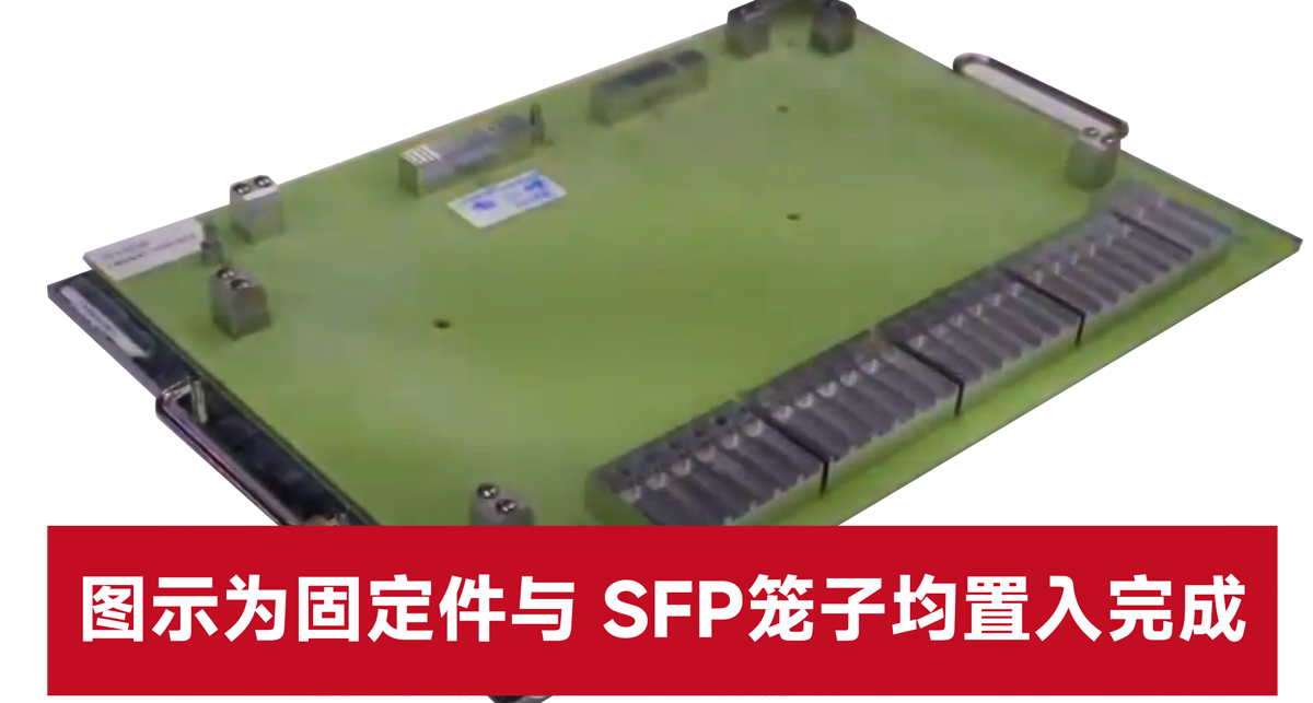
③ Place the PCB board for three-stage crimping
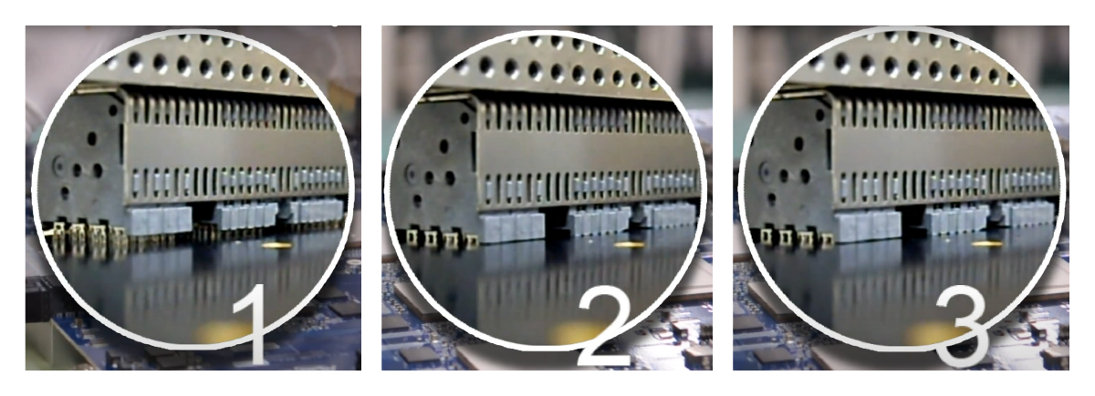
4. Key parameters of SFP optical cage
Product material
Cage material: white copper, stainless steel
Cage plating: nickel
Light guide column: optical polycarbonate
Connector material: phosphor bronze
Connector plating: contact gold plating
Casing material: LCP
Temperature range
Operating temperature: -40℃ to +105℃
Storage temperature: -40℃ to +105℃
Mechanical properties
Durability: support plugging and unplugging 100+ times
Optical module pull-out force: 15Nmax
Optical module insertion force: 40Nmax
Electrical performance
Support hot plugging
Operating voltage: 30V DC Withstand voltage: 300V AC
Operating current: 0.5A (signal), 5A (power supply)
Differential impedance: 100Ω ± 10Ω
Insulation resistance: 1000mΩ min
Contact resistance: 80mΩ max, Δ20mΩ max
Note: The minimum board thickness of the press-fit pin cage and connector combined PCB is 1.57±0.10mm (0.0625")
V. Product reliability test
Take SFP+ 2x4 connector as an example
The test was conducted on the 2x4 product version equipped with gaskets and metal EMI shrapnel. The performance data presented is related to these configurations and should be used as a reference for other product configurations.
Shielding performance test
1. Test procedure and sequence
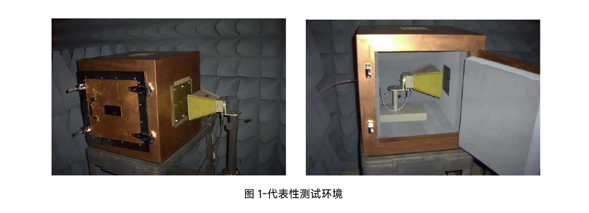
The shielding effect data was collected using a cubic copper housing with a device for connecting the device under test (DUT) mounting plate. The mounting plate is fixed to a square cutout on one side of the copper housing. There are two different mounting plates, one with a hole for the connector and the other without.
For the measurement, two horn antennas were used in the test. One was placed inside the housing and the other outside the housing. The two antennas were as close to the mounting plate as possible, about a few inches.
The performance goal is to design a shielding layer to minimize the signal power transmitted from one antenna to another.
First, a few reference measurements were made.
1. The sealed enclosure was measured with a mounting plate without holes. We use this measurement to determine the noise “floor”.
2. The DUT board was measured with only holes and no connectors installed. We use this measurement as an “upper bound” for the worst-case leakage energy without shielding.
3. The antennas were measured without any obstructions between them. This is shown as the dark black line within the upper bound. Three samples of the Design Under Test (DUT) were then measured.
The first DUT was a 2x4 SFP connector with an EMI metal gasket (orange line). See Figure 2 and Figure 3.
The second DUT was a 2x4 SFP+ connector with an EMI flex gasket (green line). See Figure 2
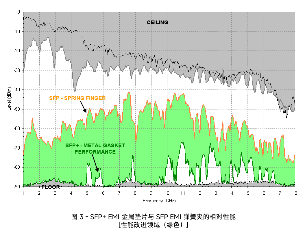
The third DUT was a 2x4 SFP+ connector with an EMI metal gasket (green line). See Figure 3
Note that the DUT did not include any connected cables or SFP/SFP+ modules. The focus of the measurements is to compare and evaluate different cage technologies. Once the modules or cables are installed, their performance parameters will dominate.
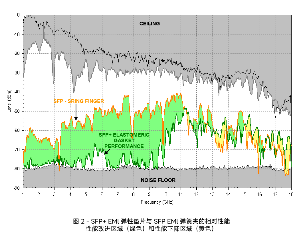
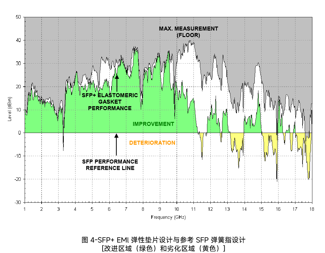
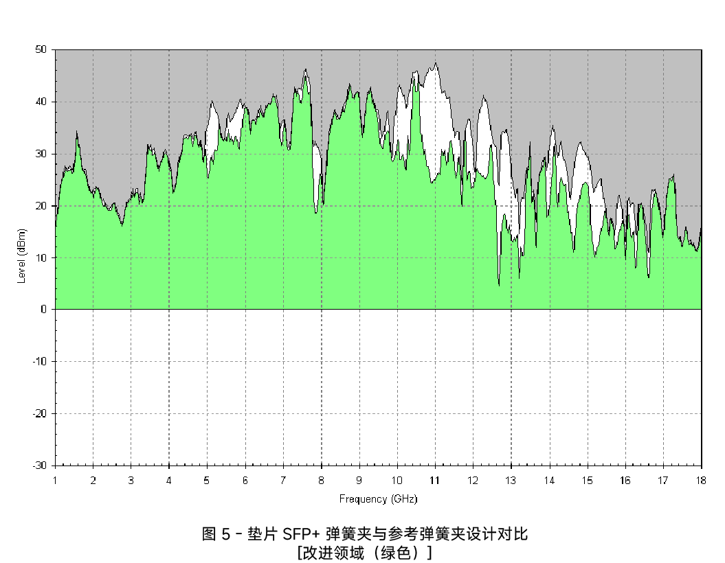
The following figure shows the performance comparison of the SFP+ elastomeric gasket design versus the SFP spring clip design. The green shaded area indicates that the elastomeric gasket performs better than the SFP spring clip, and the yellow shaded area indicates that the performance of the two complements each other.
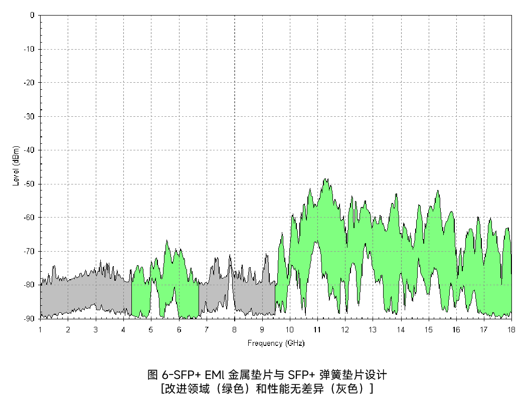
The following graph shows the performance of the SFP+ metal gasket design compared to the SFP spring clip design. The green shaded area indicates where the elastomeric gasket outperforms the SFP spring clip.
Harsh environment test Passed
Humidity resistance/constant temperature and humidity
Salt spray test;
Temperature resistance test/temperature life
Electrical performance test Passed
EMI test
Contact retention endurance test
Electrostatic breakdown test
High-speed signal test
Material test Passed
Durability test
Metal bending strength test
Insertion force and life test;
Mechanical shock/drop test
Vibration test
Shielding effect data was collected using a cubic copper housing with a device for connecting the device under test (DUT) mounting plate. The mounting plate is fixed to a square cutout on one side of the copper housing. There are two different mounting plates, one with holes for connectors and one without.
For the measurements, two horn antennas were used in the test. One was placed inside the housing and the other outside. The two antennas are placed as close to the mounting plate as possible, about a few inches.
The performance goal is to design a shield that minimizes the signal power transferred from one antenna to the other.
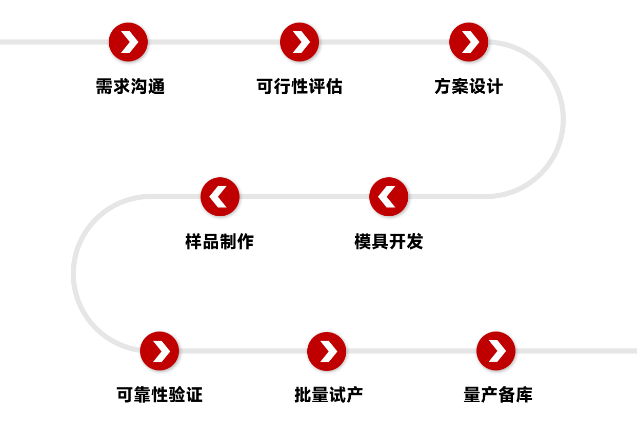
6. Product non-standard customization process
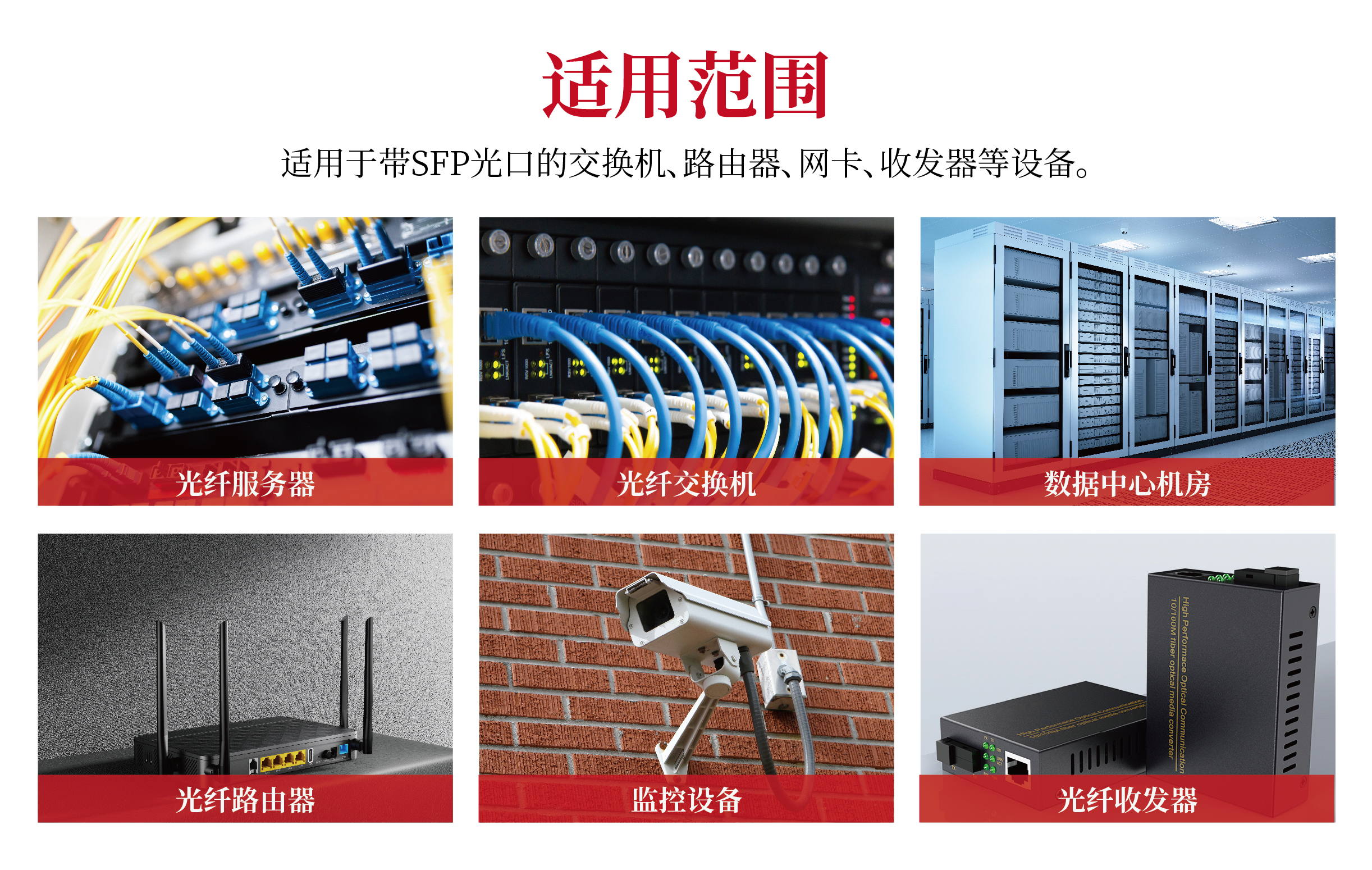
7. Application scenarios of SFP optical cages
Data centers: used in network devices such as servers, switches, routers, etc. to achieve high-speed data transmission.
Telecommunication networks: widely used in long-distance optical fiber communications to ensure the stability and reliability of data transmission.
Enterprise networks: used for internal network construction of enterprises to provide efficient and stable data transmission solutions.
1. Concept and function of optical cage
① What is optical cage?
SFP Cage (Small Form-factor Pluggable Cage) is the core mechanical and electrical interface component used to install and fix optical modules in communication equipment. It has a metal frame structure, which is composed of upper and lower covers and EMI shrapnel. It can add parts such as heat sink or light guide rod, and be crimped or welded on the equipment PCB (such as switch, router motherboard). It provides a physical slot for the optical module and realizes the connection between the optical module and the PCB board. Therefore, it is often called SFP optical cage or SFP connector.
② What are the core functions of the optical cage?
1. Electrical connection and signal integrity
2. Electromagnetic shielding (EMI Suppression)
3. Mechanical fixation and module protection
4. Heat dissipation management and dust prevention
5. Other auxiliary functions: status indication and mis-insertion prevention with light guide
2. Product components and material composition of each part
SFP optical cage is usually composed of a metal shielding shell and a connector core, and other accessories such as light guide, heat sink, etc. can be integrated according to needs.
Metal shielding shell:
It is composed of shielding shell + locking mechanism. Its main material is generally white copper or stainless steel. The plating and thickness are optional, usually nickel plating 30μ”-50μ” or no nickel plating.
Connector core:
It is composed of a base and signal terminal. The number of socket PIN is 20PIN. The processing method is surface mounting. It needs to be used with a single-layer optical cage when applied. The connector terminal is copper alloy or phosphor copper. The gold plating method is contact gold plating, and the gold plating thickness is optional.
Other accessories:
Light guide column - made of optical polycarbonate
Radiator - made of AL 6063
2. Product classification and selection of SFP optical cages
1. Product classification
① Classification by speed
② Classification by product structure
③ Classification by product accessories
2. Selection Recommendations
Steps for SFP Cage Selection
1. Define Requirements
Determine the rate:
• Steps: Select a cage that supports 1G, 10G, 25G, 100G, 200G, 400G, 800G according to network requirements.
Determine the fiber type:
• Steps: Select a cage that supports single-mode or multi-mode fiber. If long-distance transmission is required, select a cage that supports single-mode fiber.
Determine the interface type:
• Steps: Select a cage with LC, SC, or FC interface.
2. Match the device
Check the device specifications:
• Steps: Make sure that the electrical and mechanical parameters of the cage are consistent with the device.
Reference compatibility list:
• Steps: Refer to the compatibility list of the device manufacturer to ensure that the cage is compatible with the device.
3. Evaluate the cost
Cage cost:
• Steps: Consider the unit price and bulk purchase cost of the cage.
Maintenance cost:
• Steps: Consider the reliability and maintenance cost of the cage.
Selection Guide for Special Scenarios
1. High-density cabling in data centers
High-density cages:
• Features: Support high-density cabling and reduce space occupancy.
• Recommendations: Select cages that support high-density cabling, such as QSFP cages.
Heat management:
• Features: High-power modules require good heat dissipation design.
• Recommendations: Select cages with heat sinks or heat pipes to ensure heat dissipation.
2. Harsh industrial environments
Reinforced design:
• Features: Corrosion-resistant, high-strength materials, such as stainless steel.
• Recommendations: Select cages made of stainless steel to ensure reliability in harsh environments.
Extended temperature range:
• Features: Supports a temperature range of -40℃ to +85℃.
• Recommendations: Select cages that support an extended temperature range to ensure stability in extreme environments.
3. Long-distance transmission
Support long-distance modules:
• Features: Modules that support long-distance transmission, such as 100km 10GBASE-ZR modules.
• Recommendation: Choose a cage that supports long-distance transmission to ensure signal quality.
Dispersion compensation:
• Features: Long-distance transmission requires a dispersion compensation module.
• Recommendation: Choose a cage that supports dispersion compensation to ensure signal quality for long-distance transmission.
III. Installation methods and fixtures
1. The difference between press-fit and soldering
Press-fit connection, as the name implies, is to press a pin with an interference size into a through hole drilled on the circuit board. The basic element is that the diameter of the pin's joint area must be larger than the hole diameter. This causes the material of the mating surface of the pin and the hole to deform, and the deformation of the pin or the through hole will also maintain the tight fit between the two.
Press-fit is divided into solid pin pins and fisheye pins (see the figure below for details)
1. Solid pin pins, the force that maintains good contact between the pin and the through hole is the elastic deformation force of the through hole.
2. Elastic deformation (fisheye pin EoN) The force that maintains good contact between the pin and the through hole is the elastic deformation force of the pin.
Compared with solid pins, elastic pins have lower requirements for the dimensional accuracy of PCB metallized through holes; smaller insertion force; and allow multiple plugging and unplugging in the metallized through holes of the same PCBA (good maintainability). Therefore, in the current PCBA processing crimping process, elastically deformable pins or fisheye pins are mainly used.
Welding connection, welding is a hot processing process, the pin is placed in the through hole, and the connection is achieved through molten solder.
2. Press-fit installation steps
Installing a press-fit SFP optical cage requires the use of a dedicated press-fit machine and a press-fit fixture, using a three-stage press-in method for press-fitting.
① Place the crimping jig flat on the crimping table
② Place the positioning block and SFP cage on the corresponding positions of the crimping fixture.
③ Place the PCB board for three-stage crimping
4. Key parameters of SFP optical cage
Product material
Cage material: white copper, stainless steel
Cage plating: nickel
Light guide column: optical polycarbonate
Connector material: phosphor bronze
Connector plating: contact gold plating
Casing material: LCP
Temperature range
Operating temperature: -40℃ to +105℃
Storage temperature: -40℃ to +105℃
Mechanical properties
Durability: support plugging and unplugging 100+ times
Optical module pull-out force: 15Nmax
Optical module insertion force: 40Nmax
Electrical performance
Support hot plugging
Operating voltage: 30V DC Withstand voltage: 300V AC
Operating current: 0.5A (signal), 5A (power supply)
Differential impedance: 100Ω ± 10Ω
Insulation resistance: 1000mΩ min
Contact resistance: 80mΩ max, Δ20mΩ max
Note: The minimum board thickness of the press-fit pin cage and connector combined PCB is 1.57±0.10mm (0.0625")
V. Product reliability test
Take SFP+ 2x4 connector as an example
The test was conducted on the 2x4 product version equipped with gaskets and metal EMI shrapnel. The performance data presented is related to these configurations and should be used as a reference for other product configurations.
Shielding performance test
1. Test procedure and sequence
The shielding effect data was collected using a cubic copper housing with a device for connecting the device under test (DUT) mounting plate. The mounting plate is fixed to a square cutout on one side of the copper housing. There are two different mounting plates, one with a hole for the connector and the other without.
For the measurement, two horn antennas were used in the test. One was placed inside the housing and the other outside the housing. The two antennas were as close to the mounting plate as possible, about a few inches.
The performance goal is to design a shielding layer to minimize the signal power transmitted from one antenna to another.
First, a few reference measurements were made.
1. The sealed enclosure was measured with a mounting plate without holes. We use this measurement to determine the noise “floor”.
2. The DUT board was measured with only holes and no connectors installed. We use this measurement as an “upper bound” for the worst-case leakage energy without shielding.
3. The antennas were measured without any obstructions between them. This is shown as the dark black line within the upper bound. Three samples of the Design Under Test (DUT) were then measured.
The first DUT was a 2x4 SFP connector with an EMI metal gasket (orange line). See Figure 2 and Figure 3.
The second DUT was a 2x4 SFP+ connector with an EMI flex gasket (green line). See Figure 2
The third DUT was a 2x4 SFP+ connector with an EMI metal gasket (green line). See Figure 3
Note that the DUT did not include any connected cables or SFP/SFP+ modules. The focus of the measurements is to compare and evaluate different cage technologies. Once the modules or cables are installed, their performance parameters will dominate.
The following figure shows the performance comparison of the SFP+ elastomeric gasket design versus the SFP spring clip design. The green shaded area indicates that the elastomeric gasket performs better than the SFP spring clip, and the yellow shaded area indicates that the performance of the two complements each other.
The following graph shows the performance of the SFP+ metal gasket design compared to the SFP spring clip design. The green shaded area indicates where the elastomeric gasket outperforms the SFP spring clip.
Harsh environment test Passed
Humidity resistance/constant temperature and humidity
Salt spray test;
Temperature resistance test/temperature life
Electrical performance test Passed
EMI test
Contact retention endurance test
Electrostatic breakdown test
High-speed signal test
Material test Passed
Durability test
Metal bending strength test
Insertion force and life test;
Mechanical shock/drop test
Vibration test
Shielding effect data was collected using a cubic copper housing with a device for connecting the device under test (DUT) mounting plate. The mounting plate is fixed to a square cutout on one side of the copper housing. There are two different mounting plates, one with holes for connectors and one without.
For the measurements, two horn antennas were used in the test. One was placed inside the housing and the other outside. The two antennas are placed as close to the mounting plate as possible, about a few inches.
The performance goal is to design a shield that minimizes the signal power transferred from one antenna to the other.
6. Product non-standard customization process
7. Application scenarios of SFP optical cages
Data centers: used in network devices such as servers, switches, routers, etc. to achieve high-speed data transmission.
Telecommunication networks: widely used in long-distance optical fiber communications to ensure the stability and reliability of data transmission.
Enterprise networks: used for internal network construction of enterprises to provide efficient and stable data transmission solutions.
share to

Newsletter subscription
Subscribe to our newsletter and stay updated on the latest information of our company and product.
Name
|
Subscribe
I agree that the information that I provide will be used in accordance with the terms of Voohu International Inc. Privacy & Cookies Policy


