


Working principle of push-pull converter
A push-pull DC/DC converter, or simply push-pull converter, is a power electronic device that uses two power switching transistors to alternately switch on and off to achieve DC/DC conversion. It can be viewed as a combination of two single-transistor forward DC/DC converters, and its output rectification and filtering circuits are basically the same as those of a forward DC/DC converter.
VOOHU Electronics Technology, with nine years of experience in the communications electronics field, has launched a push-pull converter solution, featuring a compact push-pull transformer that reconfigures power isolation solutions with millimeter-level dimensions. It is available in various package types, such as WHST06E, WHST060, WHST06D, and WHST06L.
Topology of Push-Pull DC/DC Converter
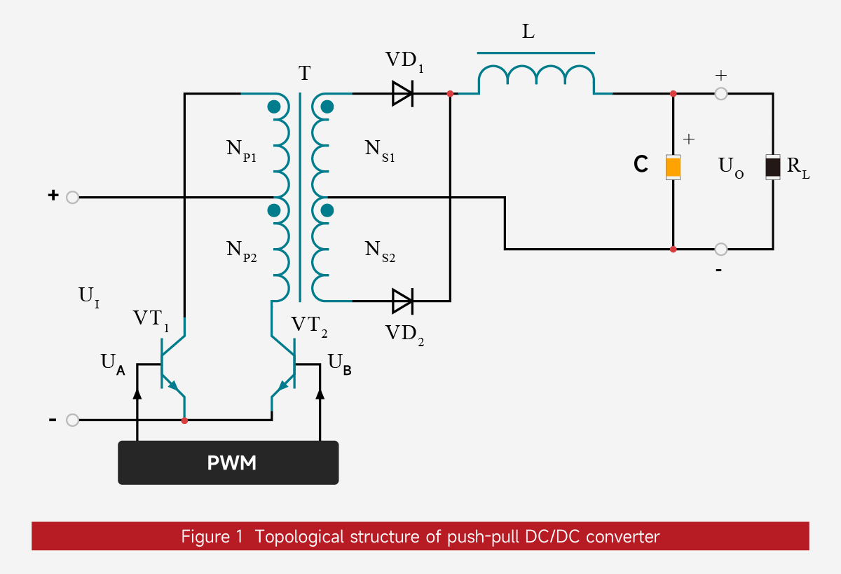
The topology of a push-pull DC/DC converter is shown in Figure 1. The core components and their parameters are defined as follows:
High-frequency push-pull transformer (T):
Contains primary windings (NP1、NP2) and secondary windings (NS1、NS2). Both primary and secondary windings have center taps.NP1 and NP2 have the same number of turns, and NS1 and NS2 have the same number of turns. The polarities of the primary and secondary windings are consistent, and the positions of the corresponding terminals are marked in the figure.
Power switching transistors (VT1、VT2):
Generally, transistors or MOSFETs are used to control the circuit's on/off state.
Output rectifier diodes (VD1、VD2):
Rectify the secondary induced voltage and unify the current direction.
Output filter components:
Filter inductor (L), filter capacitor (C), used to stabilize the output voltage and current and prevent sudden changes.
Load and output:
External load resistor (R), DC output voltage (UO);
Control core:
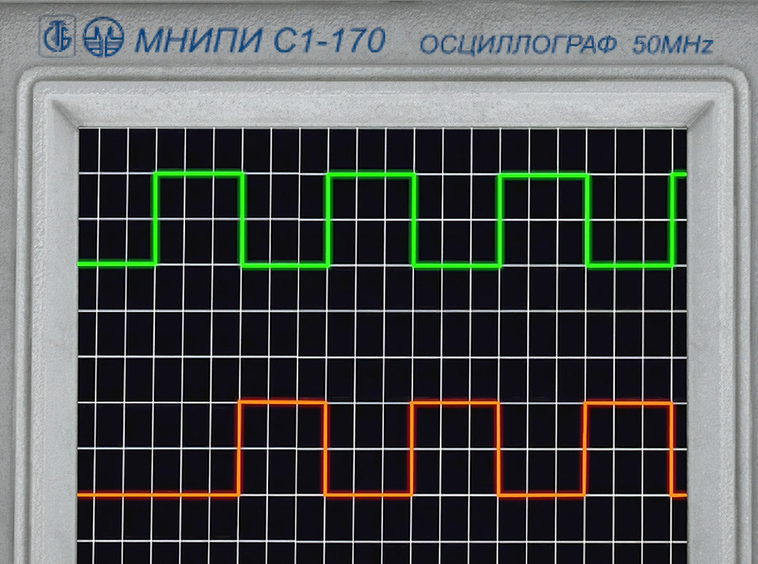
Pulse width modulator (PWM), generates two control signals (UA,UB) with a 180° phase difference to drive... VT1 and VT2 work alternately, and the PWM duty cycle is theoretically less than 50%, which generates a dead zone.
Working Principle of Push-Pull DC/DC Converter
The control signals UA and UB output by the pulse width modulator (PWM) are alternately complementary: when UA is high, UB is low, and vice versa. Power switches VT1、VT2 alternately turn on and off under the control of the PWM signal (equivalent to a high-speed mechanical switch); for ease of analysis, the on/off states of switches S1、S2 correspond to the on and off states of VT1、VT2, respectively.
VT1 On (VT2 Off) State
When UA is high, VT1 is on and VT2 is off. The current path is shown in Figure 2:
The input voltage (UI) is applied across the primary winding NP1, and the primary current (IP1) increases linearly. The polarity of the induced electromotive force (EMF) in NP1 is "-" at the top and "+" at the bottom.
According to the principle of electromagnetic induction, the polarity of the induced voltages in the primary winding NP2 and the secondary windings NS1 and NS2 is "-" at the top and "+" at the bottom. At this time, VD1 is off and VD2 is on.
The induced voltage (US2) in the secondary winding NS2 acts on the left end of the filter inductor L, forming a linearly increasing secondary current (IS2, i.e., the forward current of VD2). The energy stored in the inductor L increases, and its induced EMF polarity is "+" on the left and "-" on the right.
IS2 charges the filter capacitor C (charging current I1) and provides the output current (IO) to the load RL, satisfying IS2 = ... I1 + IO.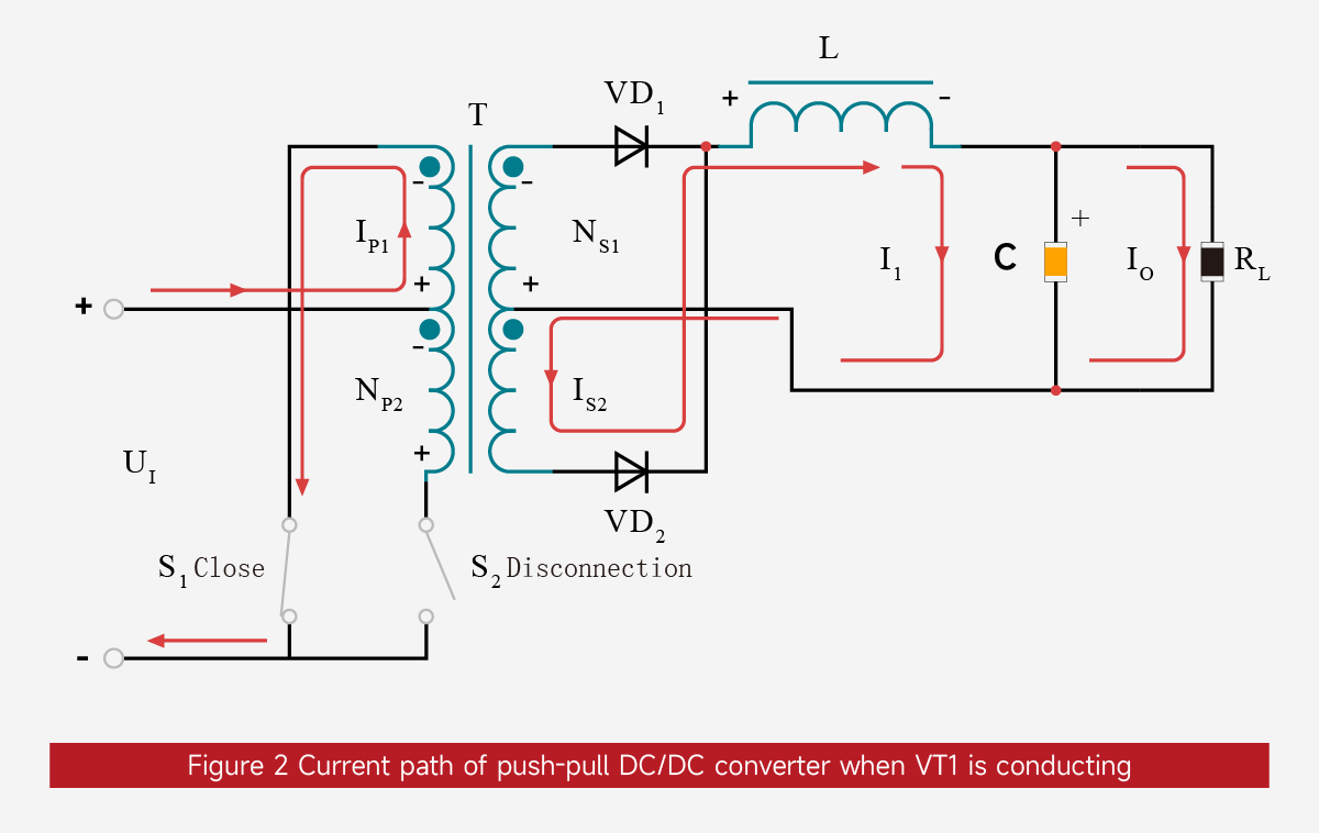
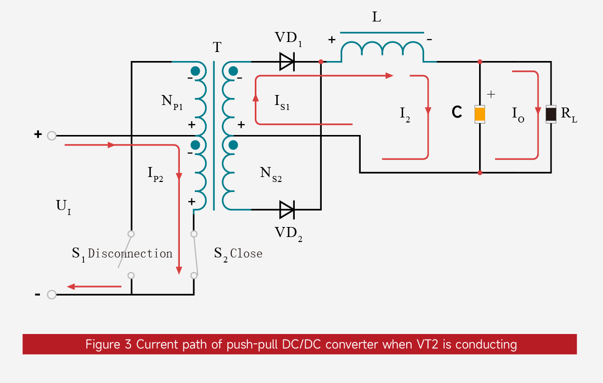
VT2 On (VT1 Off) State
When UB is high, VT2 is on and VT1 is off. The current path is shown in Figure 3:
The input voltage (UI) is applied across the primary winding NP2, and the primary current (IP2) increases linearly. The polarity of the induced electromotive force (EMF) of NP2 is "+" at the top and "-" at the bottom.
According to the principle of electromagnetic induction, the polarity of the induced voltages of the primary winding NP1 and the secondary windings NS1 and NS2 is "+" at the top and "-" at the bottom. At this time, VD1 is on and VD2 is off.
The induced voltage (US1) of the secondary winding NS1 acts on the left end of the filter inductor L, forming a linearly increasing secondary current (IS1, i.e., the forward current of VD1). The energy stored in the inductor L increases, and its induced EMF polarity is "+" on the left and "-" on the right.
IS1 charges the filter capacitor C (charging current I2) on one hand, and provides the output current (IO) to the load RL on the other hand, satisfying IS1 = ... I2 + IO.
Dead Time Design
When the PWM control signal duty cycle (D) is < 50%, there will be a period of time when both UA and UB are low. To avoid short-circuit damage caused by VT1 and VT2 conducting simultaneously, a dead time (DT) needs to be reserved, typically set to 1~3μs; and the smaller the duty cycle D, the longer the period of time when both UA and UB are low.
Tip:
To eliminate the risk of both power switches conducting simultaneously, the duty cycle (D) of the two control signals output by the pulse width modulator (PWM) must be strictly less than 50%.
Founded in 2018 and with its overseas expansion planned for 2025, VOOHU Electronics has become a reliable partner for over 1000 companies thanks to its "superior quality, reasonable prices, attentive service, and reliable delivery."
If you're also looking for a "worry-free, cost-effective, and convenient" supplier of communication electronic components, consider VOOHU. After all, the choice of over 100 listed companies is a sure bet.
Choose VOOHU – truly reliable. This isn't just a slogan; it's the answer written with the trust of over 1000 customers over 8 years.
VOOHU Electronics Technology, with nine years of experience in the communications electronics field, has launched a push-pull converter solution, featuring a compact push-pull transformer that reconfigures power isolation solutions with millimeter-level dimensions. It is available in various package types, such as WHST06E, WHST060, WHST06D, and WHST06L.
Topology of Push-Pull DC/DC Converter
The topology of a push-pull DC/DC converter is shown in Figure 1. The core components and their parameters are defined as follows:
High-frequency push-pull transformer (T):
Contains primary windings (NP1、NP2) and secondary windings (NS1、NS2). Both primary and secondary windings have center taps.NP1 and NP2 have the same number of turns, and NS1 and NS2 have the same number of turns. The polarities of the primary and secondary windings are consistent, and the positions of the corresponding terminals are marked in the figure.
Power switching transistors (VT1、VT2):
Generally, transistors or MOSFETs are used to control the circuit's on/off state.
Output rectifier diodes (VD1、VD2):
Rectify the secondary induced voltage and unify the current direction.
Output filter components:
Filter inductor (L), filter capacitor (C), used to stabilize the output voltage and current and prevent sudden changes.
Load and output:
External load resistor (R), DC output voltage (UO);
Control core:
Pulse width modulator (PWM), generates two control signals (UA,UB) with a 180° phase difference to drive... VT1 and VT2 work alternately, and the PWM duty cycle is theoretically less than 50%, which generates a dead zone.
Working Principle of Push-Pull DC/DC Converter
The control signals UA and UB output by the pulse width modulator (PWM) are alternately complementary: when UA is high, UB is low, and vice versa. Power switches VT1、VT2 alternately turn on and off under the control of the PWM signal (equivalent to a high-speed mechanical switch); for ease of analysis, the on/off states of switches S1、S2 correspond to the on and off states of VT1、VT2, respectively.
VT1 On (VT2 Off) State
When UA is high, VT1 is on and VT2 is off. The current path is shown in Figure 2:
The input voltage (UI) is applied across the primary winding NP1, and the primary current (IP1) increases linearly. The polarity of the induced electromotive force (EMF) in NP1 is "-" at the top and "+" at the bottom.
According to the principle of electromagnetic induction, the polarity of the induced voltages in the primary winding NP2 and the secondary windings NS1 and NS2 is "-" at the top and "+" at the bottom. At this time, VD1 is off and VD2 is on.
The induced voltage (US2) in the secondary winding NS2 acts on the left end of the filter inductor L, forming a linearly increasing secondary current (IS2, i.e., the forward current of VD2). The energy stored in the inductor L increases, and its induced EMF polarity is "+" on the left and "-" on the right.
IS2 charges the filter capacitor C (charging current I1) and provides the output current (IO) to the load RL, satisfying IS2 = ... I1 + IO.
VT2 On (VT1 Off) State
When UB is high, VT2 is on and VT1 is off. The current path is shown in Figure 3:
The input voltage (UI) is applied across the primary winding NP2, and the primary current (IP2) increases linearly. The polarity of the induced electromotive force (EMF) of NP2 is "+" at the top and "-" at the bottom.
According to the principle of electromagnetic induction, the polarity of the induced voltages of the primary winding NP1 and the secondary windings NS1 and NS2 is "+" at the top and "-" at the bottom. At this time, VD1 is on and VD2 is off.
The induced voltage (US1) of the secondary winding NS1 acts on the left end of the filter inductor L, forming a linearly increasing secondary current (IS1, i.e., the forward current of VD1). The energy stored in the inductor L increases, and its induced EMF polarity is "+" on the left and "-" on the right.
IS1 charges the filter capacitor C (charging current I2) on one hand, and provides the output current (IO) to the load RL on the other hand, satisfying IS1 = ... I2 + IO.
Dead Time Design
When the PWM control signal duty cycle (D) is < 50%, there will be a period of time when both UA and UB are low. To avoid short-circuit damage caused by VT1 and VT2 conducting simultaneously, a dead time (DT) needs to be reserved, typically set to 1~3μs; and the smaller the duty cycle D, the longer the period of time when both UA and UB are low.
Tip:
To eliminate the risk of both power switches conducting simultaneously, the duty cycle (D) of the two control signals output by the pulse width modulator (PWM) must be strictly less than 50%.
Founded in 2018 and with its overseas expansion planned for 2025, VOOHU Electronics has become a reliable partner for over 1000 companies thanks to its "superior quality, reasonable prices, attentive service, and reliable delivery."
If you're also looking for a "worry-free, cost-effective, and convenient" supplier of communication electronic components, consider VOOHU. After all, the choice of over 100 listed companies is a sure bet.
Choose VOOHU – truly reliable. This isn't just a slogan; it's the answer written with the trust of over 1000 customers over 8 years.
share to
Related links
02 Core technical specifications and risk prevention and control guidelines for network transformer wiring
04 [Circuit Standard Design] Reference for Gigabit Discrete and Integrated RJ45 Standard Circuit Design
Newsletter subscription
Subscribe to our newsletter and stay updated on the latest information of our company and product.
Name
|
Subscribe
I agree that the information that I provide will be used in accordance with the terms of Voohu International Inc. Privacy & Cookies Policy


