【FAQ】Three FAQs for integrated RJ45 (Mag-Jack) application
The integrated network port (Mag-Jack) integrates the network transformer, common mode inductor, Bob Smith termination and indicator light inside the RJ45. Its pins include differential pins, center taps, NC, GND, LED and other different functions, and the connection methods are different. Most of the three types of problems, such as network port failure, indicator light not lighting, and EMC failure, are not damaged components, but incorrect pin wiring.
VOOHU Electronics (VOOHU) explains these three types of common wiring errors in four parts: phenomenon, root cause, correct approach, and self-test, for reference in network port design and debugging.
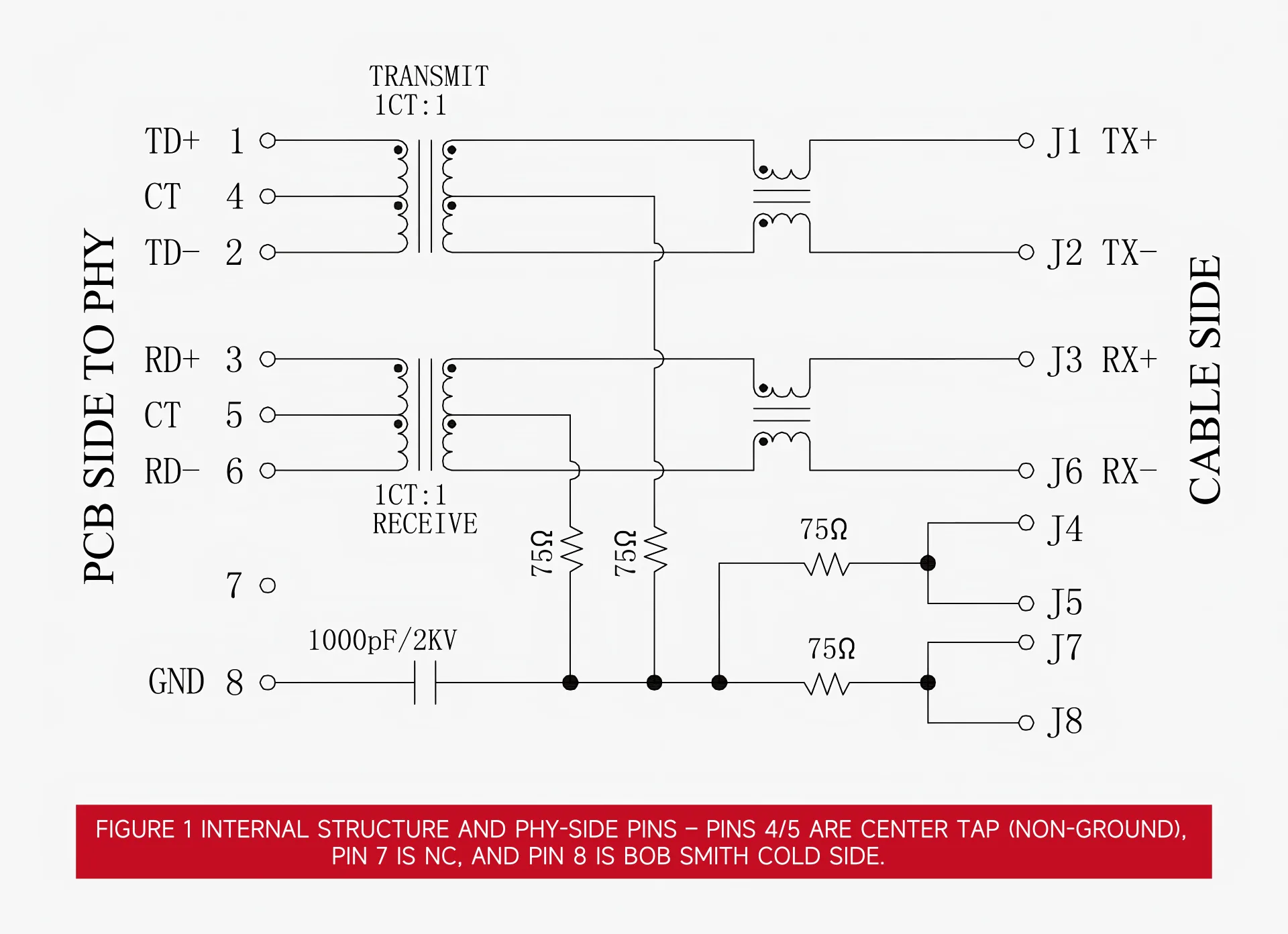
Device internal structure and pin definition
The integrated network port integrates the transformer, common mode inductor, Bob Smith termination, and indicator light inside the RJ45. The pins also include different functions such as differential pins, center taps, NC, GND, and LED. Before wiring, the definition should be confirmed pin by pin according to the specification sheet.
Problem 1: The network port is blocked/the abnormal transmission center tap is improperly grounded
Typical phenomena:
The link cannot be established, packets are lost occasionally, the transmit eye diagram becomes worse, and the PHY becomes too hot.
Root cause:
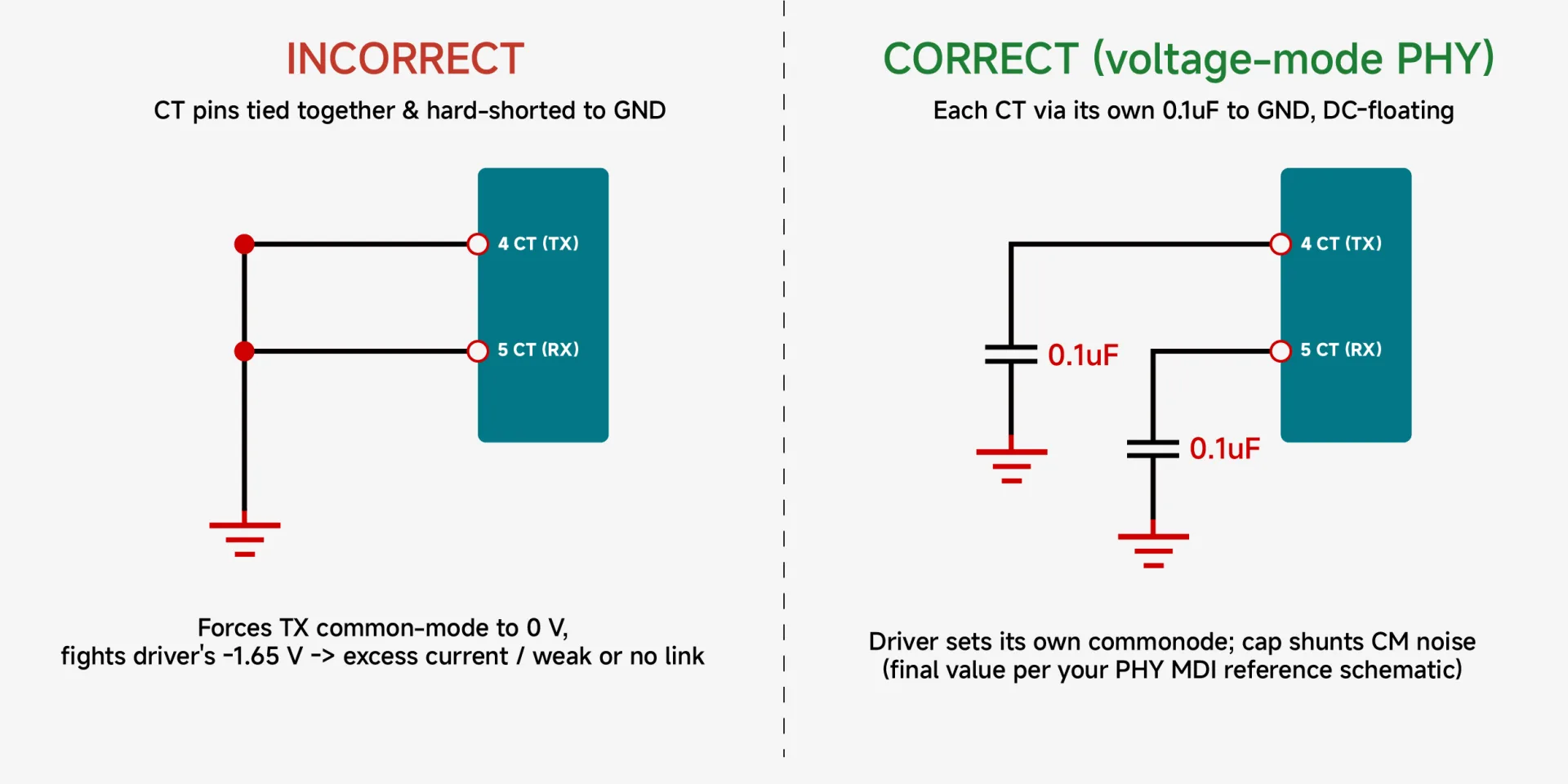
pin4/5 is the center tap on the PHY side of the transformer, not ground. The center tap connection depends on the PHY’s transmit driver type:
Current mode PHY (such as TI DP83822):
The transmitting stage needs to inject bias current through the center tap, and the center tap must be connected to the power supply (AVDD/VCC). Floating or hard grounding will cause the driver to lack bias current and cause abnormal transmission.
Voltage type PHY (such as Jinglue JL1111B):
The transmitting stage self-establishes the common mode level (see the PHY manual for specific values), requiring the center tap DC to be floating and only connected to ground via a capacitor. A hard ground will short out the common mode levels.
In both cases, the center tap should not be directly hard grounded.
Correct approach:
Processed according to PHY driver type, and subject to the MDI reference circuit in the PHY manual:
Current type:
The center tap is connected to the power supply through magnetic beads/filter, and then decoupled to the ground nearby.
Voltage type:
Each center tap is connected to the signal ground via a 0.1µF capacitor, keeping the DC floating; the TX and RX center taps are decoupled separately (one for each pin, not in parallel) to reduce crosstalk.
Problem 2: The indicator light does not light up and the LED polarity is reversed.
Typical phenomena:
One of the LINK / ACT indicators is not on, usually the one connected in the opposite way to the other one.
Root cause:
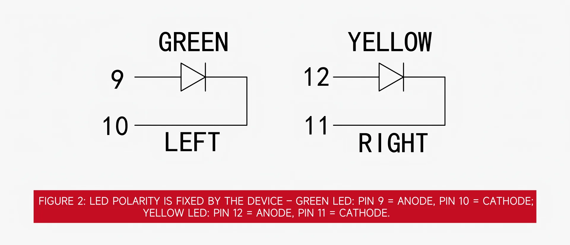
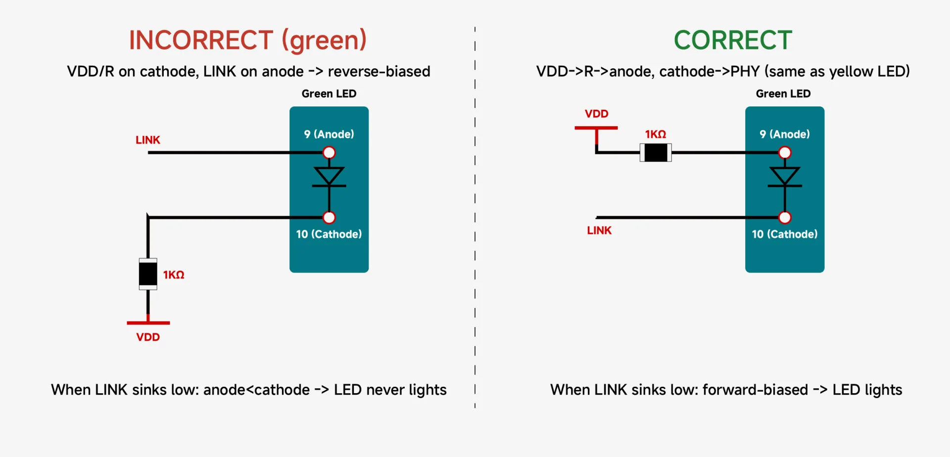
The LINK / ACT indicator pins of PHY are mostly driven by low-level current sinks (open-drain is pulled low to light up). The standard topology is: VDD → current-limiting resistor → LED anode, LED cathode → PHY indicator pin. If the current limiting resistor/VDD is connected to the cathode and the PHY indicator pin is connected to the anode, the LED will be reverse biased and will not light up. The LED anode/cathode of the integrated network port are fixed internally and cannot be inferred based on the pin number sequence.
Correct approach:
According to the specifications, each lamp is connected from the anode to VDD through the current limiting resistor and the cathode to the PHY indicator pin (the circuit direction of the two lamps is the same)
Note:
The pin order of the two lamps may not be the same. In this example (Figure 2), the green light anode is pin9, the yellow light anode is pin12, and the cathodes are both on pin10/pin11 in the middle, arranged in a mirror image. The wiring should be defined according to the anode/cathode of each lamp, and the same foot sequence cannot be applied, otherwise the reverse bias will not light up.
The current limiting resistor is set according to VDD and the target brightness, and does not exceed the perfusion upper limit of the PHY (commonly about 8~12mA)
Question 3: Bob Smith Grounding and Protection
Typical phenomena:
The common mode radiation exceeds the standard, the PHY is vulnerable to surge/lightning strikes, and hot-swap electrostatic damage.
Root cause:
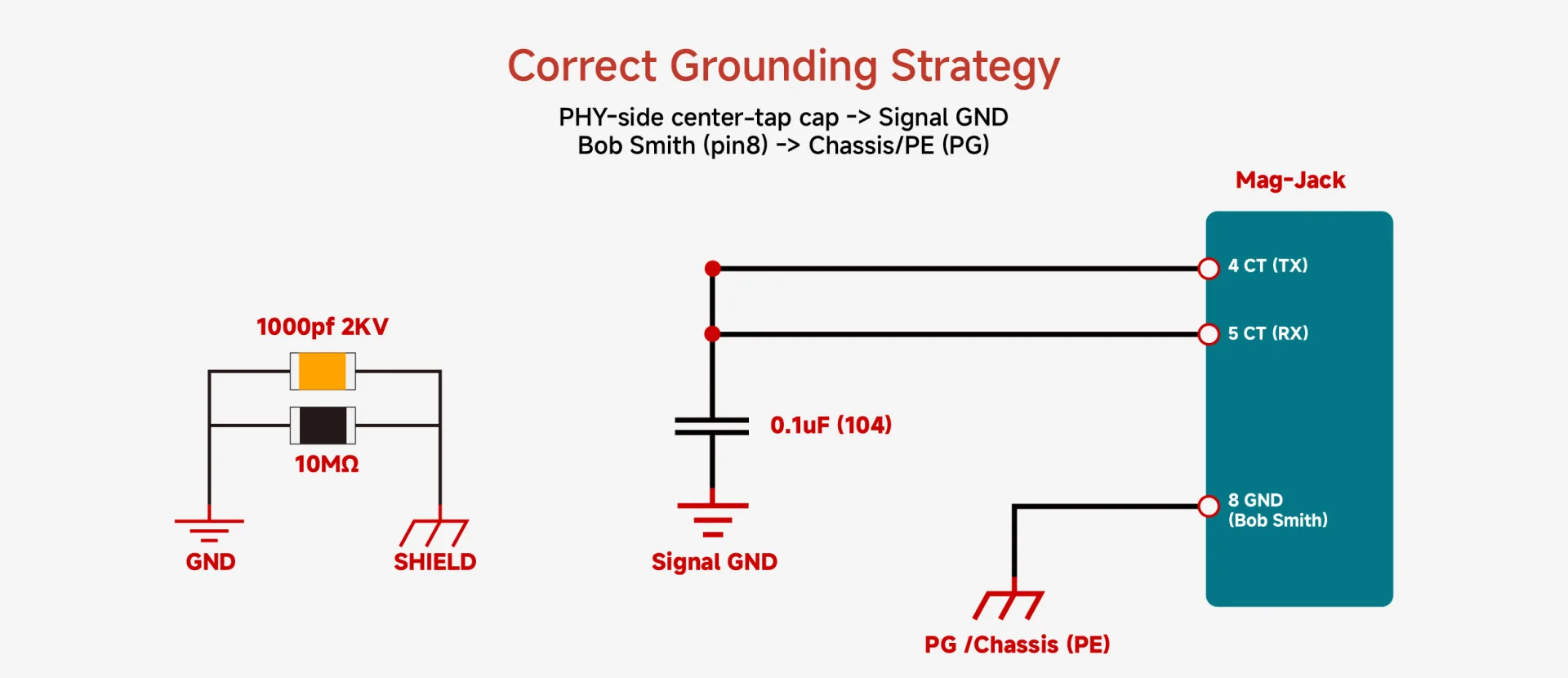
If the cold end (pin 8) of the Bob Smith termination is connected to the signal ground instead of the chassis ground, the common mode noise introduced by the cable will flow back to the signal ground, reducing the EMC margin.
If the MDI differential pair does not have ESD protection, static electricity during plugging and unplugging will directly impact the PHY.
Correct approach:
Ground:
Bob Smith The cold end (pin8) is connected to the chassis ground (PE); the signal ground and the chassis ground are connected at a single point via R (1MΩ) in parallel with C (1nF / 2kV), which provides an AC return path for common mode noise, and at the same time blocks the DC ground loop with high resistance and discharges static electricity.
ESD:
The cable-side differential pair of the integrated network port is located inside the package and cannot be lead out on the PCB. ESD can only be added to the PHY-side differential pair (between the PHY and the internal transformer), and a low junction capacitance (<1pF) array is selected to avoid affecting signal integrity.
surge:
Also subject to the limitation that the cable side cannot be drawn out, GDT + pressure sensitivity can only be added to the nodes that can be drawn out (shielding shell/Bob Smith cold end/center tap pair PE); outdoor and industrial ports should be reserved.
Summary
The integrated network port reduces the number of peripheral components, but it still requires a correct understanding of the pin definitions and PHY interface. The connection method of the center tap, LED polarity, and Bob Smith's grounding method directly affect whether the network port can be connected, whether the indicator light is on, and whether the EMC meets the standards. In the schematic design stage, by comparing the internal structure diagram of the specification and the MDI reference circuit of the PHY manual, most of these problems can be avoided before boarding.
Selection and solution support
The connectivity, EMC and reliability of the network port depend on the matching of the internal components of the integrated network port and the peripheral protection. VOOHU Electronics (VOOHU) provides matching selections from integrated network ports, network transformers, audio transformers to common mode inductors and TVS/ESD/GDT protection devices, covering the isolation, filtering and protection links of the signal chain. This support capability has been systematically integrated into VOOHU's eight major solution systems - from data communications, industrial control to energy storage BMS and other application fields, helping engineers avoid the wiring and protection issues described in this article during the design stage and shorten the selection and debugging cycle.
FAQ
Q: I connected the signal to pin 1, but I can’t detect the output at pin 4. Is the transformer broken? Can the center tap of the integrated network port (such as pin4/5) be directly connected to ground?
A: No. The connection method of the center tap depends on the transmit driver type of the PHY: the current-type PHY needs to connect the center tap to the power supply to provide bias current, and the voltage-type PHY needs DC to be suspended and connected to ground only through the capacitor. Direct hard grounding will cause abnormal transmission (current type) or the common mode level to be short-circuited (voltage type). For details, please refer to the MDI reference circuit in the PHY manual.
Q: How to determine whether the PHY in your hand is current type or voltage type?
A: Check the transmit driver description or MDI reference circuit in the PHY data sheet: those with the center tap connected to power supply are mostly current type (such as TI DP83822), while those with center tap not connected to power supply and only capacitor decoupling are voltage type (such as ADI ADIN1200). If you are unsure, you can provide the PHY model to VOOHU electronic technical support to help confirm the center tap connection and provide the corresponding reference circuit.
Q: Only one of the two indicator lights is on. Is the device broken?
A: Most of the time the LED polarity is reversed rather than damaged. The LED anode/cathode of the integrated network port are fixed internally, and the pin sequence of the two lamps may be mirrored (see Figure 2 of this article), and the same pin sequence cannot be applied. Just follow the specifications and connect the anode/cathode of each lamp according to the PHY drive polarity.
Q: The integrated network port already contains a transformer, do I need additional ESD/surge protection?
A: Most of the time the LED polarity is reversed rather than damaged. The LED anode/cathode of the integrated network port are fixed internally, and the pin sequence of the two lamps may be mirrored (see Figure 2 of this article), and the same pin sequence cannot be applied. Just follow the specifications and connect the anode/cathode of each lamp according to the PHY drive polarity.
Q: How to quickly confirm whether the integrated network port itself is normal when incoming materials in batches? What support can VOOHU provide?
A: VOOHU Electronics can provide incoming material judgment standards and test conditions for corresponding models, and provide reference circuits for center taps, LEDs, grounding, and protection according to PHY drive types to help quickly locate problems and shorten the debugging cycle in the design and incoming material links.
VOOHU Electronics (VOOHU) explains these three types of common wiring errors in four parts: phenomenon, root cause, correct approach, and self-test, for reference in network port design and debugging.
Device internal structure and pin definition
The integrated network port integrates the transformer, common mode inductor, Bob Smith termination, and indicator light inside the RJ45. The pins also include different functions such as differential pins, center taps, NC, GND, and LED. Before wiring, the definition should be confirmed pin by pin according to the specification sheet.
Problem 1: The network port is blocked/the abnormal transmission center tap is improperly grounded
Typical phenomena:
The link cannot be established, packets are lost occasionally, the transmit eye diagram becomes worse, and the PHY becomes too hot.
Root cause:
pin4/5 is the center tap on the PHY side of the transformer, not ground. The center tap connection depends on the PHY’s transmit driver type:
Current mode PHY (such as TI DP83822):
The transmitting stage needs to inject bias current through the center tap, and the center tap must be connected to the power supply (AVDD/VCC). Floating or hard grounding will cause the driver to lack bias current and cause abnormal transmission.
Voltage type PHY (such as Jinglue JL1111B):
The transmitting stage self-establishes the common mode level (see the PHY manual for specific values), requiring the center tap DC to be floating and only connected to ground via a capacitor. A hard ground will short out the common mode levels.
In both cases, the center tap should not be directly hard grounded.
Correct approach:
Processed according to PHY driver type, and subject to the MDI reference circuit in the PHY manual:
Current type:
The center tap is connected to the power supply through magnetic beads/filter, and then decoupled to the ground nearby.
Voltage type:
Each center tap is connected to the signal ground via a 0.1µF capacitor, keeping the DC floating; the TX and RX center taps are decoupled separately (one for each pin, not in parallel) to reduce crosstalk.
Problem 2: The indicator light does not light up and the LED polarity is reversed.
Typical phenomena:
One of the LINK / ACT indicators is not on, usually the one connected in the opposite way to the other one.
Root cause:
The LINK / ACT indicator pins of PHY are mostly driven by low-level current sinks (open-drain is pulled low to light up). The standard topology is: VDD → current-limiting resistor → LED anode, LED cathode → PHY indicator pin. If the current limiting resistor/VDD is connected to the cathode and the PHY indicator pin is connected to the anode, the LED will be reverse biased and will not light up. The LED anode/cathode of the integrated network port are fixed internally and cannot be inferred based on the pin number sequence.
Correct approach:
According to the specifications, each lamp is connected from the anode to VDD through the current limiting resistor and the cathode to the PHY indicator pin (the circuit direction of the two lamps is the same)
Note:
The pin order of the two lamps may not be the same. In this example (Figure 2), the green light anode is pin9, the yellow light anode is pin12, and the cathodes are both on pin10/pin11 in the middle, arranged in a mirror image. The wiring should be defined according to the anode/cathode of each lamp, and the same foot sequence cannot be applied, otherwise the reverse bias will not light up.
The current limiting resistor is set according to VDD and the target brightness, and does not exceed the perfusion upper limit of the PHY (commonly about 8~12mA)
Question 3: Bob Smith Grounding and Protection
Typical phenomena:
The common mode radiation exceeds the standard, the PHY is vulnerable to surge/lightning strikes, and hot-swap electrostatic damage.
Root cause:
If the cold end (pin 8) of the Bob Smith termination is connected to the signal ground instead of the chassis ground, the common mode noise introduced by the cable will flow back to the signal ground, reducing the EMC margin.
If the MDI differential pair does not have ESD protection, static electricity during plugging and unplugging will directly impact the PHY.
Correct approach:
Ground:
Bob Smith The cold end (pin8) is connected to the chassis ground (PE); the signal ground and the chassis ground are connected at a single point via R (1MΩ) in parallel with C (1nF / 2kV), which provides an AC return path for common mode noise, and at the same time blocks the DC ground loop with high resistance and discharges static electricity.
ESD:
The cable-side differential pair of the integrated network port is located inside the package and cannot be lead out on the PCB. ESD can only be added to the PHY-side differential pair (between the PHY and the internal transformer), and a low junction capacitance (<1pF) array is selected to avoid affecting signal integrity.
surge:
Also subject to the limitation that the cable side cannot be drawn out, GDT + pressure sensitivity can only be added to the nodes that can be drawn out (shielding shell/Bob Smith cold end/center tap pair PE); outdoor and industrial ports should be reserved.
Summary
The integrated network port reduces the number of peripheral components, but it still requires a correct understanding of the pin definitions and PHY interface. The connection method of the center tap, LED polarity, and Bob Smith's grounding method directly affect whether the network port can be connected, whether the indicator light is on, and whether the EMC meets the standards. In the schematic design stage, by comparing the internal structure diagram of the specification and the MDI reference circuit of the PHY manual, most of these problems can be avoided before boarding.
Selection and solution support
The connectivity, EMC and reliability of the network port depend on the matching of the internal components of the integrated network port and the peripheral protection. VOOHU Electronics (VOOHU) provides matching selections from integrated network ports, network transformers, audio transformers to common mode inductors and TVS/ESD/GDT protection devices, covering the isolation, filtering and protection links of the signal chain. This support capability has been systematically integrated into VOOHU's eight major solution systems - from data communications, industrial control to energy storage BMS and other application fields, helping engineers avoid the wiring and protection issues described in this article during the design stage and shorten the selection and debugging cycle.
FAQ
Q: I connected the signal to pin 1, but I can’t detect the output at pin 4. Is the transformer broken? Can the center tap of the integrated network port (such as pin4/5) be directly connected to ground?
A: No. The connection method of the center tap depends on the transmit driver type of the PHY: the current-type PHY needs to connect the center tap to the power supply to provide bias current, and the voltage-type PHY needs DC to be suspended and connected to ground only through the capacitor. Direct hard grounding will cause abnormal transmission (current type) or the common mode level to be short-circuited (voltage type). For details, please refer to the MDI reference circuit in the PHY manual.
Q: How to determine whether the PHY in your hand is current type or voltage type?
A: Check the transmit driver description or MDI reference circuit in the PHY data sheet: those with the center tap connected to power supply are mostly current type (such as TI DP83822), while those with center tap not connected to power supply and only capacitor decoupling are voltage type (such as ADI ADIN1200). If you are unsure, you can provide the PHY model to VOOHU electronic technical support to help confirm the center tap connection and provide the corresponding reference circuit.
Q: Only one of the two indicator lights is on. Is the device broken?
A: Most of the time the LED polarity is reversed rather than damaged. The LED anode/cathode of the integrated network port are fixed internally, and the pin sequence of the two lamps may be mirrored (see Figure 2 of this article), and the same pin sequence cannot be applied. Just follow the specifications and connect the anode/cathode of each lamp according to the PHY drive polarity.
Q: The integrated network port already contains a transformer, do I need additional ESD/surge protection?
A: Most of the time the LED polarity is reversed rather than damaged. The LED anode/cathode of the integrated network port are fixed internally, and the pin sequence of the two lamps may be mirrored (see Figure 2 of this article), and the same pin sequence cannot be applied. Just follow the specifications and connect the anode/cathode of each lamp according to the PHY drive polarity.
Q: How to quickly confirm whether the integrated network port itself is normal when incoming materials in batches? What support can VOOHU provide?
A: VOOHU Electronics can provide incoming material judgment standards and test conditions for corresponding models, and provide reference circuits for center taps, LEDs, grounding, and protection according to PHY drive types to help quickly locate problems and shorten the debugging cycle in the design and incoming material links.
Share to
Related links