Pin count
Sets the number of winding taps and the board footprint. Parts with different pin counts are not drop-in replacements for each other.
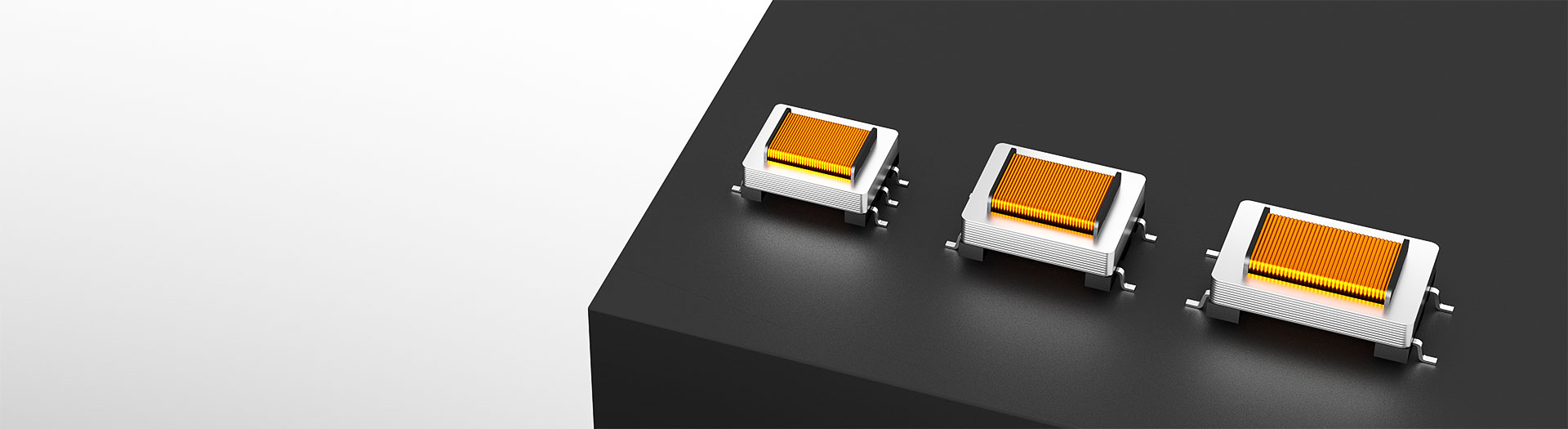
Transformer products
A four-pin package brings out both ends of each winding and nothing else, which suits a straightforward isolation or impedance-matching stage. Compare AC impedance, turns ratio and dielectric strength, then confirm the pin pitch and height against the board before ordering samples.
Part number search & selector
The table uses the current English-site product records, published selection fields and part-specific technical-file links.
* Frozen Image and Part Number columns · drag horizontally to review all specifications
| Image | Datasheet | Compare | Downloads |
Pins
|
L/W/H(mm*mm*mm)
|
AC impedance PRI:SEC(Ω)
|
DC resistance PRI:SEC(Ω)
|
Turn Ratio(PRI:SEC)
|
Mounting Method
|
Hi-Pot(AC)
|
Insertion Loss(dB)
|
Insertion Loss (dB)
|
Sample |
|---|
| Image | Part number | Datasheet | Compare | Downloads | Pins | L/W/H(mm*mm*mm) | AC impedance PRI:SEC(Ω) | DC resistance PRI:SEC(Ω) | Turn Ratio(PRI:SEC) | Mounting Method | Hi-Pot(AC) | Insertion Loss(dB) | Insertion Loss (dB) | Sample |
|---|---|---|---|---|---|---|---|---|---|---|---|---|---|---|
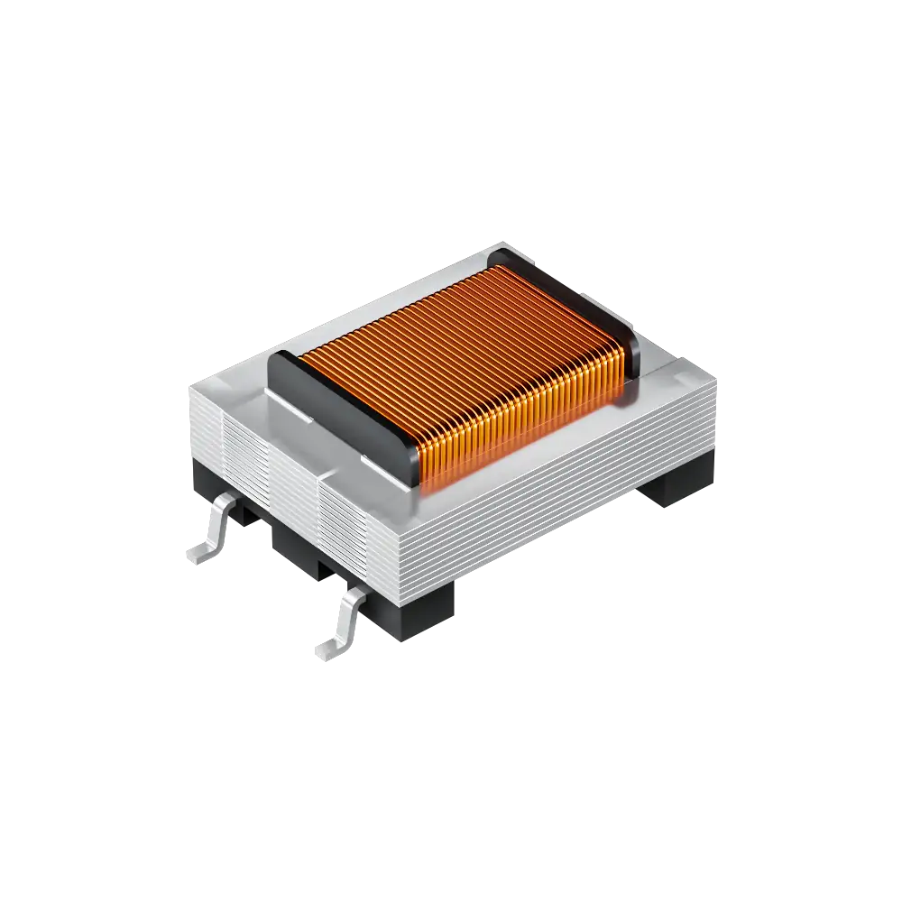 |
WHATC-05-042AR | SPEC | 4 PIN | 14*8*4.4 | 600:400 | 105:105 | 1±1% | SMD | 1250V | 2.3 | — |
|
||
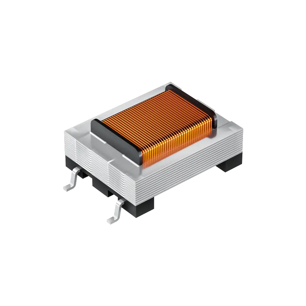 |
WHTT4205 | SPEC | 4 PIN | 20.5*8.5*4.5 | 20000:20000 | 2370:2820 | 1±1% | SMD | 1250V | 1.3±0.5 | — |
|
||
|
|
WHTT4203 | SPEC | 4 PIN | 20.9*8.5*4.5 | 600:287 | 155:144 | 1±2% | SMD | 1650V | 3.5 | — |
|
||
|
|
WHTT4204 | SPEC | 4 PIN | 18.2*8.5*4.6 | 600:290 | 141:171 | 1±1% | SMD | 1250V | 3.3±0.2 | — |
|
||
|
|
WHTT4202 | SPEC | 4 PIN | 18.2*8.5*4.6 | 600:287 | 180:160 | 1±1% | SMD | 1650V | 3.5 | — |
|
||
|
|
WHTT4201 | SPEC | 4 PIN | 18.5*5.08*4.6 | 600:287 | 155:144 | 1±2% | SMD | 1650V | - | — |
|
||
|
|
WHTT4103 | SPEC | 4 PIN | 15.2*8.2*5 | 600:600 | 62:3.2 | 6±1% | SMD | 1250V | - | — |
|
||
|
|
WHTT4102 | SPEC | 4 PIN | 15.6*8.5*5 | 600:400 | 118:140 | 1±2% | SMD | 1500V | 3.85 | — |
|
||
|
|
WHTT4101 | SPEC | 4 PIN | 15.2*8.2*4.9 | 600:600 | 160:133 | 1±3% | SMD | 1250V | - | — |
|
||
|
|
WHTT4100 | SPEC | 4 PIN | 15.2*8*5.08 | 600:301 | 150:150 | 1±1% | SMD | 1250V | 3.3±0.25 | — |
|
||
|
|
WHTT4V150 | SPEC | 4 PIN | 11*8.2*5 | 600:600 | 73:73 | 1±1% | SMD | 1250V | 1.5 | — |
|
||
|
|
WHTT40013 | SPEC | 4 PIN | 14*8*4.4 | 600:346 | 157:146 | 1±1% | SMD | 1250V | 2.9±0.1 | — |
|
||
|
|
WHTT4009 | SPEC | 4 PIN | 11*8.2*5 | 600:600 | 160:135 | 1±2% | SMD | 1000V | - | — |
|
||
|
|
WHTT4006 | SPEC | 4 PIN | 14.5*8.2*5 | 600:600 | 48:42 | 1±2% | SMD | 1250V | 1 | — |
|
||
|
|
WHTT4005 | SPEC | 4 PIN | 11*8.2*5 | 600:600 | 160:135 | 1±2% | SMD | 1250V | - | — |
|
||
|
|
WHTT4002 | SPEC | 4 PIN | 15.2*8.2*5 | 600:400 | 62:3.2 | 6±1% | SMD | 1250V | - | — |
|
||
|
|
WHTT4001 | SPEC | 4 PIN | 14*8.15*5.08 | 600:600 | 140:170 | 1±2% | SMD | 1000V | - | — |
|
Broaden the selected filters or clear the current search.
By pin count
Pin count sets the winding taps and the board footprint, so start from the circuit you have.
How to select
Work from the source and load impedance outward to the mechanical constraints.
State the source impedance, load impedance, signal level and frequency range, and whether the stage has to convert balanced to unbalanced.
The impedance ratio is the square of the turns ratio. A 600:600 part is 1:1; stepping 600 down to 150 ohm needs a 2:1 turns ratio.
Confirm the maximum signal level the core can carry without saturating, then confirm the dielectric strength the safety case demands.
Match pin count, pin pitch and height against the board, then verify insertion loss and frequency response on your own hardware.
Parameters
Each figure is measured under stated conditions; read the conditions with the number.
Sets the number of winding taps and the board footprint. Parts with different pin counts are not drop-in replacements for each other.
Quoted for a stated frequency, commonly 1 kHz. Read the test frequency with the value; the same part reads differently elsewhere in the band.
Fixes the impedance transformation and the voltage relationship between windings. Impedance ratio equals turns ratio squared.
Winding copper loss. It adds to insertion loss and matters most when the winding also carries a bias current.
The isolation the barrier withstands under the stated test. Choose against the safety requirement, not against the working voltage alone.
Signal lost through the transformer at the stated frequency. Compare candidates at the same frequency or the numbers do not mean the same thing.
Compare
Pin count and impedance separate the families more than package size does.
Return to the selector ↑| Pins | Parts | L/W/H(mm*mm*mm) | AC impedance PRI:SEC(Ω) | DC resistance PRI:SEC(Ω) | Turn Ratio(PRI:SEC) | Mounting Method | Hi-Pot(AC) | Insertion Loss(dB) | Insertion Loss (dB) | Action |
|---|---|---|---|---|---|---|---|---|---|---|
| 4 PIN | 17 | 11*8.2*5, 14*8*4.4, 14.5*8.2*5, 14*8.15*5.08, 15.2*8.2*5, 15.2*8*5.08, 15.2*8.2*4.9, 15.6*8.5*5, 18.5*5.08*4.6, 18.2*8.5*4.6, 20.9*8.5*4.5, 20.5*8.5*4.5 | 600:287, 600:290, 600:301, 600:346, 600:400, 600:600, 20000:20000 | 140:170, 105:105, 48:42, 160:135, 157:146, 73:73, 150:150, 160:133, 118:140, 62:3.2, 155:144, 180:160, 141:171, 2370:2820 | 1±1%, 1±2%, 1±3%, 6±1% | SMD | 1000V, 1250V, 1500V, 1650V | 1, 1.3±0.5, 1.5, 2.9±0.1, 3.3±0.2, 3.3±0.25, 3.5, 3.85, -, 2.3 | Not specified | Filter → |
| 5 PIN | 5 | 14.5*8.2*5, 14.5*8.2*4.8, 14.5*8.5*5.08 | 600:600, 600:365, 600:460, 300:600, None | 120:250, 138:130, 90.5:112:102, 45:55, 65:75 | 1±1%, 1±2%, 2±1% | SMD | 500V, 1000V | 2.8, -, Not specified | 1.3, Not specified | Filter → |
| 6 PIN | 6 | 13.2*8.2*5, 13.5*9.5*7.5, 13.5*10.0*7.50, 14*8*4.4, 15.2*9.0*7.5 | 600:316, 600:412, 600:430, 10000:10000, None | 155:150, 115:115, 30:38, 50:50, 170: 170, 1620:1620 | 1±1%, 1±2%, - | SMD, DIP | 1200V, 1250V, 1500V, 3750V, 3880V, 4600V | 2, 3.0±0.25, 4.5, - | Not specified | Filter → |
Application review
Confirm line level, balanced wiring and the impedance ratio the circuit expects.
Documents
Datasheets carry the tested impedance, frequency response and recommended footprint.
Showing representative available file sets. Search to find a specific SKU.
VOOHU’s published product content is reviewed by its engineering team. Specifications, downloads and technical support information are tied to specific part numbers, so you can verify them before requesting samples or a quotation.
Category overview
Two questions come up on almost every audio transformer enquiry: what the part is actually for, and why so many datasheets quote 600 ohm.
Discuss a new design
Contact FAE for a replacement assessment.
Already have a part number? Request samples or a quote.
An audio transformer couples a signal magnetically between two windings. Nothing conducts across the barrier, so a ground loop between two pieces of equipment cannot push current through the signal path. That is what removes hum. The second job is impedance matching, so a source drives a load it can actually deliver power into.
600 ohm is a telephone and broadcast line convention rather than a law of physics. It became the reference impedance for balanced audio lines, so parts and equipment were built around it. A 600:600 transformer is a 1:1 isolation part; a 600:150 part steps impedance down by four, which is a 2:1 turns ratio.
Identify the primary, secondary and any centre tap from the datasheet pinout, not from the physical symmetry of the package. Keep the balanced pair symmetric on the board. Then measure insertion loss and frequency response on your own hardware, because the published curve is taken under the datasheet's stated source and load.
FAQ
Answers cover function, the 600 ohm convention, wiring and interchange limits.
Four pins bring out both ends of the primary and both ends of the secondary, with no centre tap. That covers the common case: isolate two stages, or match one impedance to another. If your circuit needs a centre tap for a balanced feed or phase splitting, you need a part with more pins.
When the circuit needs a tap partway along a winding. Centre taps are used for balanced drive, phase splitting and some bias arrangements. Those require five or six pins. Decide from the schematic which nodes you have to reach, then pick the pin count that exposes them.
Read the pinout from the datasheet for the specific part number. Do not infer it from the package outline, because a four-pin body is usually symmetric and gives no visual clue. Getting primary and secondary the wrong way round inverts the impedance transformation.
Not automatically. Compare turns ratio, DC resistance, maximum signal level, dielectric strength and insertion loss, and check the pin pitch and recommended footprint. Even when two parts share an impedance figure, they may be specified at different test frequencies, which makes the numbers hard to compare directly.
With a complete part number, send the part number, quantity, delivery region and the date you need it. If you are still selecting, send the source and load impedance, signal level and frequency range, and a sales engineer will confirm candidates before samples are arranged.
Engineer support
Send the candidate part number and the condition you need reviewed. Sample support can be added after the selection is clear; commercial questions may be discussed in the same engineering conversation.
Include the document revision
Temperature, isolation voltage and PoE current basis
Pin count, pitch and spacing between pin rows
To help prioritize samples and evaluation
When you need candidates and a comparison of differences
Engineering review identifies candidate parts and explains the differences.
From the selector or engineering review
Prototyping / pilot build / production
Specify sample and production timing separately
Compliance documents, material declarations or third-party reports
Samples are free of charge. Sample quantity and lead time depend on the part number and project stage. Sales will respond on business days.