Number of contacts
Two contacts describes the electrical interface, not every retention or shielding lead.

I/O Connector products
Four contacts allow the single data pair to be carried alongside additional conductors, typically for power or auxiliary signals. Which contacts carry what is defined by the system specification, so confirm the pin assignment before wiring.
Part number search & selector
The table uses the current English-site product records, published selection fields and part-specific technical-file links.
* Frozen Image and Part Number columns · drag horizontally to review all specifications
| Image | Datasheet | Compare | Downloads |
Contacts
|
Connector form factor
|
Rated current
|
Rated voltage
|
Termination method
|
Sample |
|---|
| Image | Part number | Datasheet | Compare | Downloads | Contacts | Connector form factor | Rated current | Rated voltage | Termination method | Sample |
|---|---|---|---|---|---|---|---|---|---|---|
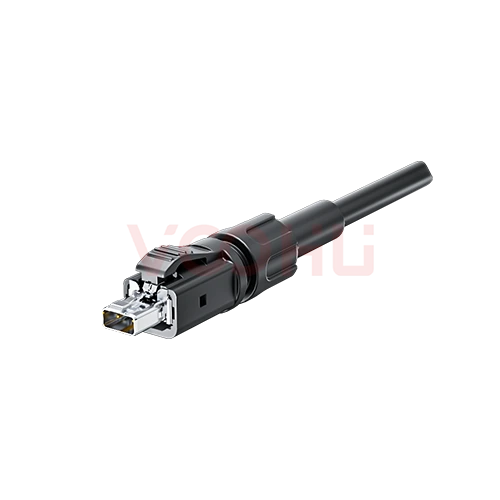 |
WHSPE00468 | SPEC | 2 PIN | Plug | 4A | 60V | Crimp |
|
||
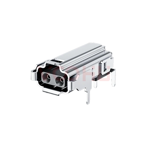 |
WHSPE00467 | SPEC | 2 PIN | Socket | 4A | 60V | THT |
|
Broaden the selected filters or clear the current search.
Product family quick links
Counts reflect the current published product data.
How to select
Narrow the published fields in sequence, compare the remaining candidates and verify the part-specific files before design-in.
Specify the equipment PHY, mating interface, cable and any power-over-data requirement.
Review the crimp process for the cable end and the footprint and assembly process for the board end.
Use controlled drawings to verify mating parts, clearances, temperature-rise and electrical conditions.
Review available files and validate samples; submit requirements even if some parameters or the final part are not yet defined.
Key selection parameters
Two contacts describes the electrical interface, not every retention or shielding lead.
Distinguish cable and board ends and confirm pairing from specified drawings.
For crimp termination, check wire size and tools; for PCB termination, check holes and solder process.
Read ratings with temperature-rise and environmental conditions; their product does not establish PoDL system power.
Confirm the interface-standard part, PHY, cable and PoDL requirements separately.
Product family comparison
Use this summary as a routing step, then verify every required value in the exact part-number row and linked technical files.
Return to the selector ↑| Contacts | Parts | Connector form factor | Rated current | Rated voltage | Termination method | Action |
|---|---|---|---|---|---|---|
| 2 PIN | 2 | Socket, Plug | 4A | 60V | THT, Crimp | Filter → |
Technical performance & application fit
Application suitability is part-number specific. Treat the catalog fields as a shortlist, then confirm the design against the linked technical files.
Downloads & technical resources
Search a full or partial SKU, then open its datasheet, 3D model or PCB footprint without returning to the product table.
Showing representative available file sets. Search to find a specific SKU.
VOOHU’s published product content is reviewed by its engineering team. Specifications, downloads and technical support information are tied to specific part numbers, so you can verify them before requesting samples or a quotation.
Category overview
SPE trades bandwidth for cable mass, and the interface is defined by a published standard rather than by contact count.
Discuss a new design
Contact FAE for a replacement assessment.
Already have a part number? Request samples or a quote.
A conventional copper Ethernet link uses two or four twisted pairs. Single Pair Ethernet carries the link on one, which cuts cable weight, diameter and connector size. That is the whole reason it exists, and it is why it suits sensors, field devices and vehicle harnesses where cable mass is a real cost.
Two contacts is the minimum an SPE link needs, but several mating faces are published for different environments. Two connectors with two contacts each will not necessarily mate. Confirm which interface standard your network specifies, and confirm it for both ends of the link.
The current listing is a cable-side crimp plug and a board-side socket. If your design needs a different mating face, a screened version or a sealed body, send the standard and the environment rather than working around the parts listed here, and our engineers will confirm what can be supplied.
FAQ & related guides
These answers guide the page workflow. Part-specific engineering limits still come from the linked technical files.
Usually power or auxiliary signals alongside the single data pair. The exact assignment is defined by the system specification rather than by the connector alone, so two four contact parts may allocate the contacts differently. Confirm the pin assignment from the documentation before wiring.
When the device needs power or additional signals delivered through the same connector rather than a separate cable. If the data pair is all that is required, the two contact version is smaller and simpler. Decide from the device's full interface requirement.
The data is still carried on one twisted pair, which is what makes it SPE. The additional contacts sit alongside that pair rather than extending the data interface. Adding contacts does not convert the link into a conventional multi-pair Ethernet connection.
Match three things: the connector mating face, the contact count, and the pin assignment the device expects. All three have to agree. A connector that mates mechanically but assigns the contacts differently will not work and may damage the device.
With a complete part number, send the part number, quantity, delivery region and the date you need it. If you are still selecting, send the interface standard, the pin assignment required and the current the power contacts must carry.
Engineer support
Send the candidate part number and the condition you need reviewed. Sample support can be added after the selection is clear; commercial questions may be discussed in the same engineering conversation.
Include the document revision
Temperature, isolation voltage and PoE current basis
Pin count, pitch and spacing between pin rows
To help prioritize samples and evaluation
When you need candidates and a comparison of differences
Engineering review identifies candidate parts and explains the differences.
From the selector or engineering review
Prototyping / pilot build / production
Specify sample and production timing separately
Compliance documents, material declarations or third-party reports
Samples are free of charge. Sample quantity and lead time depend on the part number and project stage. Sales will respond on business days.