Common mode impedance
The resistance the choke presents to common mode noise, quoted at a stated frequency. Compare candidates at the same frequency or the values do not correspond.
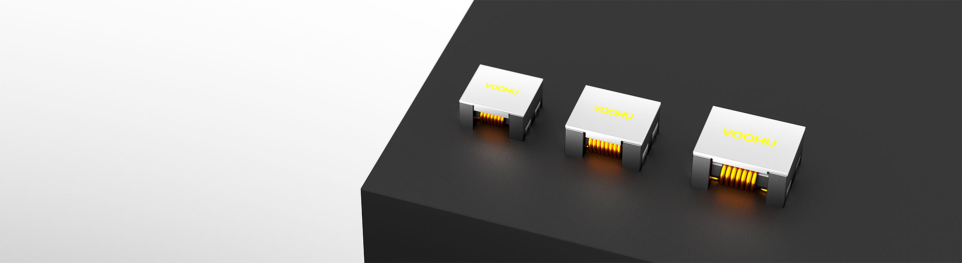
Inductor products
WHPL1211A shares a size band with WHAL1211A but carries its own specification. Similar naming is not a licence to treat them as equivalents, so read both datasheets and compare impedance at the frequency your measurement actually fails.
Part number search & selector
The table uses the current English-site product records, published selection fields and part-specific technical-file links.
* Frozen Image and Part Number columns · drag horizontally to review all specifications
| Image | Datasheet | Compare | Downloads |
Dimensions(L*W*H MAX)
|
Z(Ω) 100MHz/0.1V Min.
|
Z(Ω) 100MHz/0.1V Ref.
|
DC Resistance (mΩ) Max.
|
Rated DC Current (A)Max.
|
Insulation Resistance (MΩ)Min.
|
Rated Voltage (V)Max.
|
Sample |
|---|
| Image | Part number | Datasheet | Compare | Downloads | Dimensions(L*W*H MAX) | Z(Ω) 100MHz/0.1V Min. | Z(Ω) 100MHz/0.1V Ref. | DC Resistance (mΩ) Max. | Rated DC Current (A)Max. | Insulation Resistance (MΩ)Min. | Rated Voltage (V)Max. | Sample |
|---|---|---|---|---|---|---|---|---|---|---|---|---|
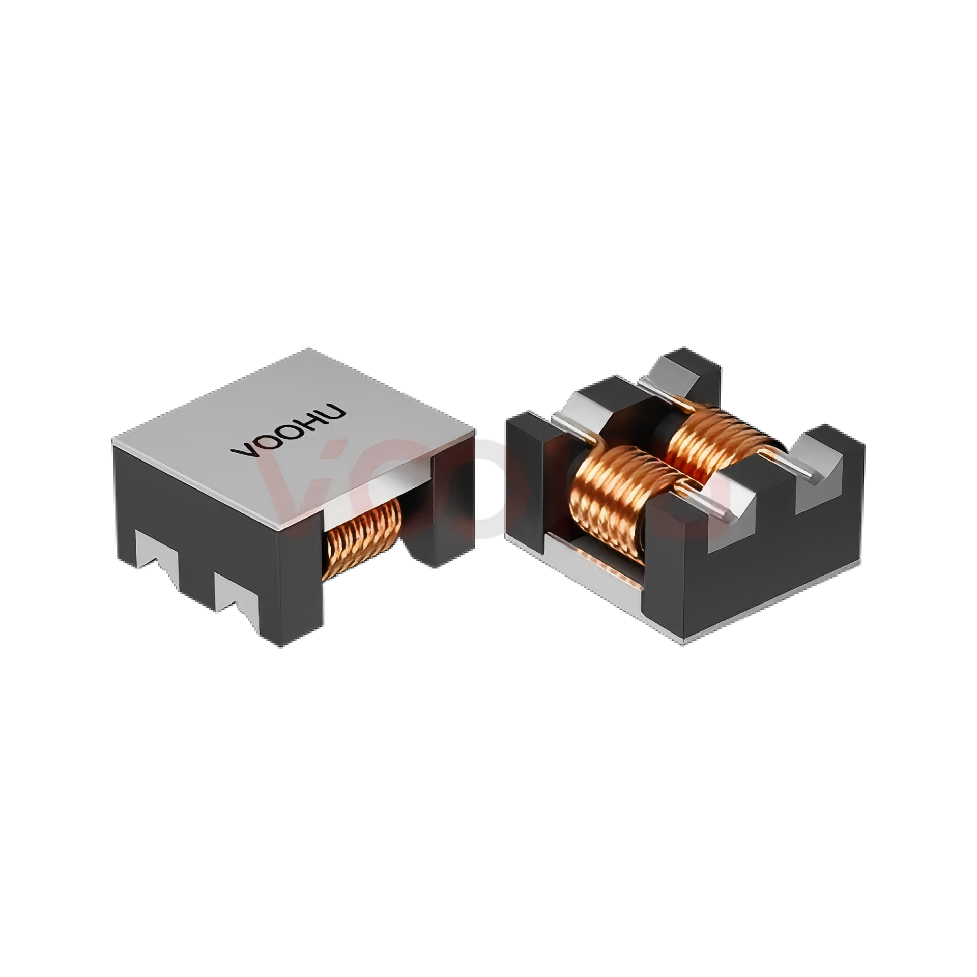 |
WHPL-1211A-231T0 | SPEC | 1211 | 80 | 230 | 4 | 10 | 10 | 125 |
|
||
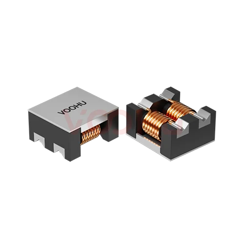 |
WHACM12A65R272 | SPEC | 1211 | 2300 | 2700 | 50 | 1.5 | 10 | 125 |
|
||
|
|
WHACM12A65R222 | SPEC | 1211 | 2200 | 2500 | 35 | 1.8 | 10 | 125 |
|
||
|
|
WHACM12A65R102 | SPEC | 1211 | 750 | 1000 | 14 | 6 | 10 | 125 |
|
||
|
|
WHACM12A65R801 | SPEC | 1211 | 600 | 800 | 8 | 8 | 10 | 125 |
|
||
|
|
WHACM12A65R701 | SPEC | 1211 | 500 | 700 | 6 | 8 | 10 | 125 |
|
||
|
|
WHACM12A65R800 | SPEC | 1211 | 80 | 230 | 2 | 10 | 10 | 125 |
|
Broaden the selected filters or clear the current search.
By series
Families differ in construction and size band, which sets impedance and current together.
How to select
Work from the failing frequency band outward to current, losses and board space.
Read the frequency range where your conducted emission scan exceeds the limit. That band, not a general noise complaint, decides which impedance curve you need.
Pick a part whose common mode impedance peaks across the failing band. Read the impedance at that frequency, not the headline figure at the family's peak.
The rated current must cover the worst-case load with margin. DC resistance sets the voltage drop and the heat the winding has to shed.
Check size, land pattern and clearance to neighbouring parts, then re-scan on your own board because layout changes the result.
Parameters
Impedance is a curve, not a single number, so read the test frequency with the value.
The resistance the choke presents to common mode noise, quoted at a stated frequency. Compare candidates at the same frequency or the values do not correspond.
The continuous current the winding carries under stated temperature-rise conditions. Derate for ambient temperature and restricted airflow inside the enclosure.
Winding resistance, usually a maximum figure. It sets the conduction loss and the voltage drop the supply has to tolerate at full load.
Measured with both windings in the common mode configuration. Higher inductance generally moves the impedance peak toward lower frequencies.
The part of the winding that does not couple. It acts on differential signals and can be useful, but it also limits how high a current the part handles.
Isolation between the two windings under a stated test. Select against the safety requirement that applies to the equipment, not the working voltage.
Compare
Size band drives impedance and current capability more than family naming does.
Return to the selector ↑| Dimensions(L*W*H MAX) | Parts | Z(Ω) 100MHz/0.1V Min. | Z(Ω) 100MHz/0.1V Ref. | DC Resistance (mΩ) Max. | Rated DC Current (A)Max. | Insulation Resistance (MΩ)Min. | Rated Voltage (V)Max. | Action |
|---|---|---|---|---|---|---|---|---|
| 1211 | 7 | 80, 500, 600, 750, 2200, 2300 | 230, 700, 800, 1000, 2500, 2700 | 2, 4, 6, 8, 14, 35, 50 | 1.5, 1.8, 6, 8, 10 | 10 | 125 | Filter → |
| 1513 | 5 | 225, 400, 500, 800, 1200 | 300, 500, 700, 1000, 1500 | 5, 6, 7, 10, 23 | 5, 9, 10, 13 | 10 | 80 | Filter → |
| 4520 | 14 | 60, 90, 180, 200, 250, 300, 350, 500, 650, 800, 1000, 1200, 1800, 2500 | 90, 150, 230, 300, 380, 420, 500, 700, 900, 1000, 1200, 1400, 2000, 3000 | 35, 40, 45, 50, 55, 58, 60, 70, 80 | 1, 1.5, 1.9, 2.0, 2.1, 2.2, 2.4, 2.5, 3, 3.2 | 10 | 50 | Filter → |
| 7060 | 9 | 40, 100, 225, 275, 500, 800, 910, 2000, 2500 | 70, 140, 300, 450, 700, 1020, 1300, 2700, 3000 | 5, 10, 15, 17, 21, 63, 75 | 0.9, 1, 2.5, 3, 4, 5, 9, 15 | 10 | 125 | Filter → |
| 9070 | 6 | 225, 450, 500, 750, 1700, 2500 | 300, 600, 700, 1000, 2200, 3000 | 6, 8, 10, 13, 60, 75 | 2.5, 3, 4, 5, 5.5, 6 | 10 | 50 | Filter → |
Application review
Confirm the line current, the failing band and how much board space the filter can take.
Documents
Datasheets carry the impedance curve, current rating and recommended land pattern.
Showing representative available file sets. Search to find a specific SKU.
VOOHU’s published product content is reviewed by its engineering team. Specifications, downloads and technical support information are tied to specific part numbers, so you can verify them before requesting samples or a quotation.
Category overview
Most selection mistakes here come from treating impedance as a single number, or from confusing common mode with differential mode noise.
Discuss a new design
Contact FAE for a replacement assessment.
Already have a part number? Request samples or a quote.
Differential noise travels out on one conductor and back on the other. Common mode noise travels the same direction on both and returns through ground. A choke winds both conductors on one core so their supply currents cancel, while common mode current sees a high impedance. That is why it filters one and passes the other.
The headline impedance figure is measured at one frequency. What matters is whether the curve is high across the band where your conducted emission scan actually fails. A part with a higher peak in the wrong place will not help. Read the curve from the datasheet, identify your failing band first, and match the two.
Rated current and DC resistance set the ceiling. A choke with excellent impedance is useless if the winding cannot carry the load current, or if its resistance drops the rail below tolerance. Check those against worst case, then confirm on your own board, because layout and the rest of the filter change the measured result.
FAQ
Answers cover how the choke works, how to read impedance and where it belongs.
The two share a size band, but impedance, rated current and DC resistance are each defined by their own datasheet. Naming similarity reflects a size convention rather than electrical equivalence. Compare the two datasheets item by item before treating either as a substitute for the other.
Verify it from the datasheet rather than assuming. Parts in the same size band often share a footprint, but pin arrangement, body tolerance and recommended pad geometry are stated per part. A mismatch that looks minor on the drawing can cause placement and reflow problems in production.
Start from your requirement, not from the part number. Identify the frequency band that fails, the line current and the board space, then read both datasheets against those three constraints. Whichever covers them with more margin is the one to sample first.
No, each part states its own. Rated current depends on winding design and the temperature rise the part was qualified to, which can differ between two parts of the same physical size. Read the figure from the specific datasheet and derate for your actual ambient conditions.
With a complete part number, send the part number, quantity, delivery region and the date you need it. If you are still selecting, send the line current, the frequency band where your scan fails and the board space available, and a sales engineer will confirm candidates first.
Engineer support
Send the candidate part number and the condition you need reviewed. Sample support can be added after the selection is clear; commercial questions may be discussed in the same engineering conversation.
Include the document revision
Temperature, isolation voltage and PoE current basis
Pin count, pitch and spacing between pin rows
To help prioritize samples and evaluation
When you need candidates and a comparison of differences
Engineering review identifies candidate parts and explains the differences.
From the selector or engineering review
Prototyping / pilot build / production
Specify sample and production timing separately
Compliance documents, material declarations or third-party reports
Sample quantity, lead time and cost depend on the project stage and part number. Sales will respond on business days.