VOOHU Electronics--RJ45 illuminated interface LED lamp position, polarity, VF/IF and PHY driver verification method
VOOHU Electronics--RJ45 illuminated interface LED lamp position, polarity, VF/IF and PHY driver verification method
The debugging process has been sorted out, I hope it will be helpful to everyone.
First, clarify the facts on both sides of the connector and PHY
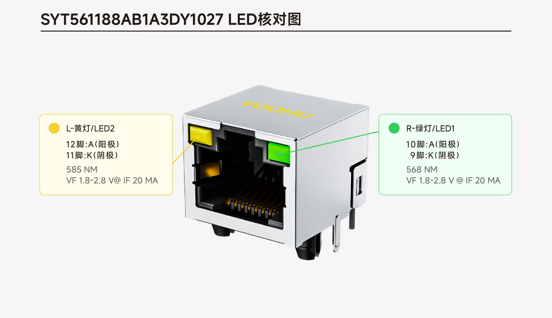
Take VOOHU SYT561188AB1A3DY1027 as an example:
The green light on the right is LED1, pin 10 is A, pin 9 is K, the wavelength is 568nm, and the VF is between 1.8~2.8V (IF=20mA). The yellow light on the left is LED2, pin 12 is A, pin 11 is K, the wavelength is 585nm, and the VF is also 1.8~2.8V (IF=20mA).
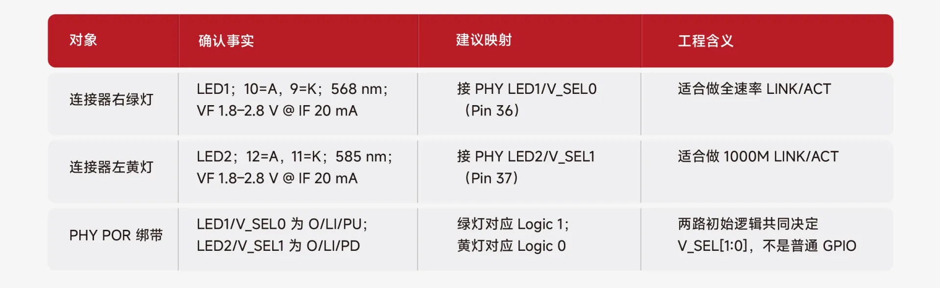
The PHY uses Jinglue JL2201B, LED1/V_SEL0 is OD/internal pull-up, and LED2/V_SEL1 is OD/internal pull-down. These two pins also serve as the strap configuration of V_SEL[1:0] when powered on, which directly determines the IO voltage of RGMII - not just ordinary GPIO.
The recommended connection method is: the green light is connected to LED1/V_SEL0, corresponding to Logic 1; the yellow light is connected to LED2/V_SEL1, corresponding to Logic 0. In this way, the V_SEL after power-on defaults to "01", which corresponds to the IODVDD=1.8V or 2.5V solution.
The recommended mapping is an engineering solution based on the A/K definition of SYT561188AB1A3DY1027 and JL2201B, which must still be confirmed by the schematic and prototype before mass production.
The LED connection method not only determines the lighting effect, but also affects the PHY power-on configuration.
Here’s where it’s easy to get stuck: the green light is Active Low, and the yellow light is Active High. If you connect them in the same direction, or just look at the labels of LED1/LED2 and swap the two pins of the PHY directly, the V_SEL logic will change when powering on. At this time, the LED may still be on, but the IO voltage of RGMII is no longer what the design expected - this kind of problem is the most troublesome to check.
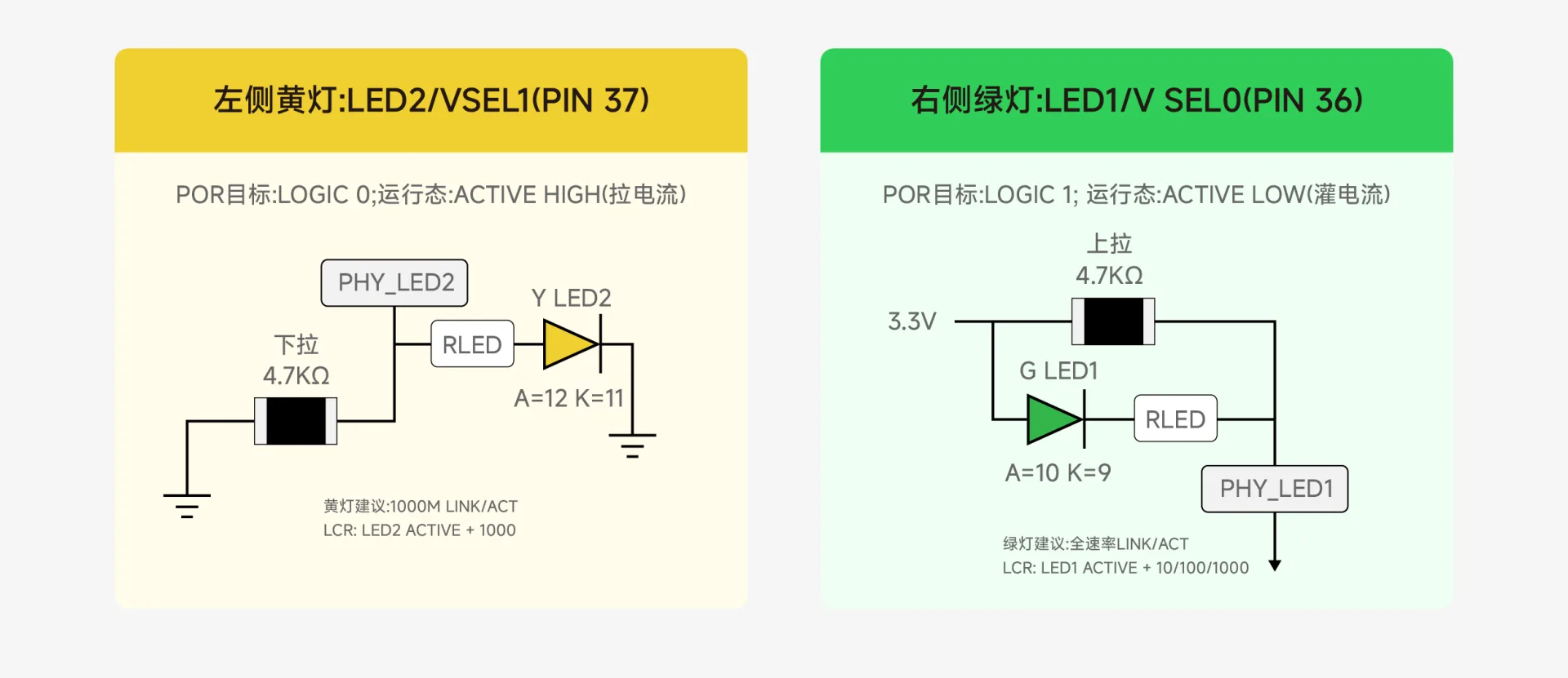
The reference path is drawn in the diagram topology: the green light goes to Logic 1 of LED1/V_SEL0, and the yellow light goes to Logic 0 of LED2/V_SEL1. 510Ω is not a universal resistance value, and different systems need to calculate it by themselves.
Lighting effect is not just "LINK/ACT": you must first select LED Mode A, and then define the speed set of each light
Lighting effect configuration is divided into two steps:
Select the mode and define the speed set for each light.
Select A (LED_MODE=0) for the global mode, so that the activity indication of each light is only bound to its own configured rate and does not interfere with each other.
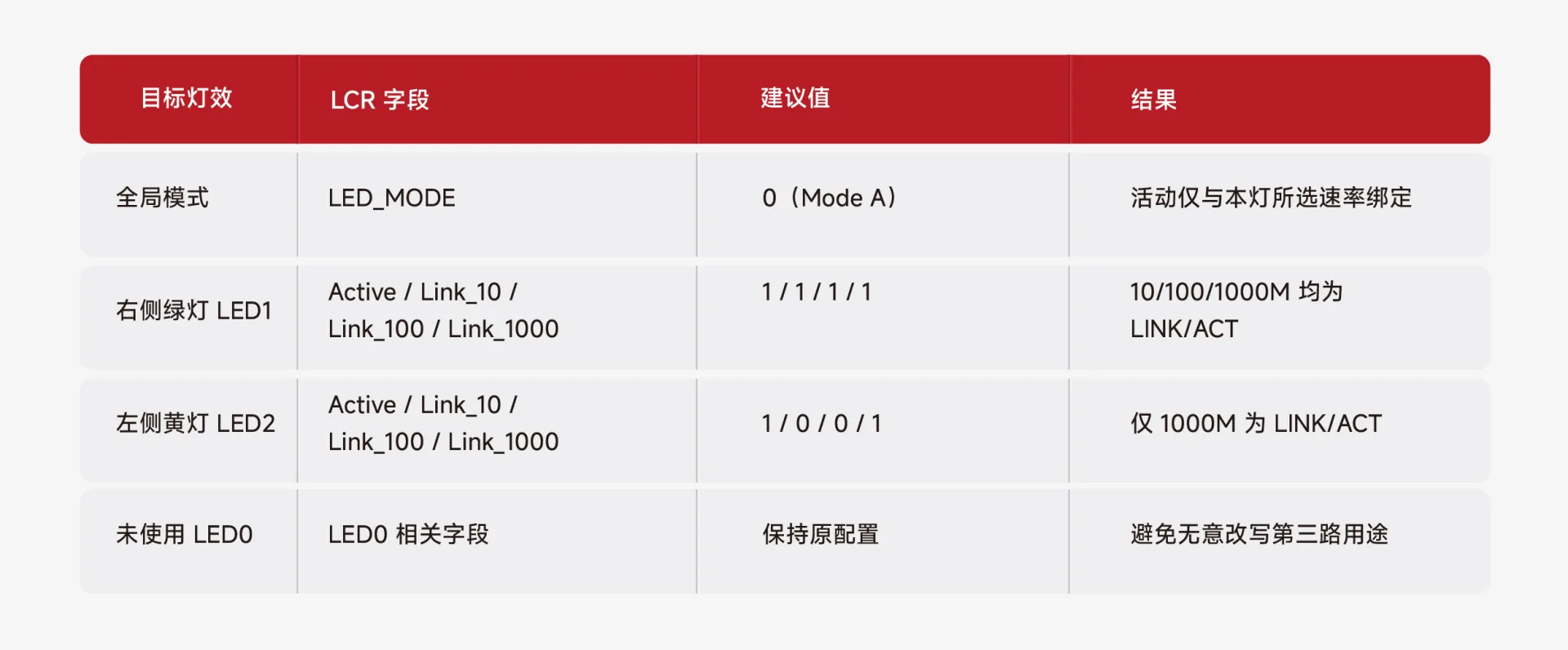
The green LED1 is configured as Active, Link_10, Link_100, and Link_1000, all of which are 1—that is, 10/100/1000M all perform LINK/ACT instructions. The yellow light LED2 is only set to 1 for Active and Link_1000, and is set to 0 for Link_10 and Link_100 - that is, it is only on when it is gigabit.
Board verification steps
1. Power off check A/K:
Use the diode scale to confirm that the green light 10=A, 9=K; the yellow light 12=A, 11=K, and check that the RLED and 4.7 kΩ network are not mirrored.
2. Confirm POR logic:
Check that LED1/V_SEL0 is Logic 1 and LED2/V_SEL1 is Logic 0; check that the target V_SEL=01 is consistent with the IODVDD scheme.
3. Read PHY first after powering on:
Confirm that MDIO is accessible and Link/Speed status is normal, and then read the current value of LCR.
4. Execute read-modify-write:
Use the diode scale to confirm that the green light 10=A, 9=K; the yellow light 12=A, 11=K, and check that the RLED and 4.7 kΩ network are not mirrored.
5.Verification
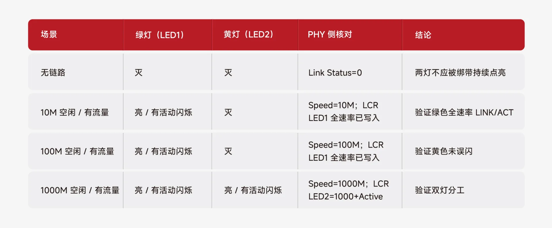
Verify step by step according to 10/100/1000M and idle/traffic combinations. Acceptance cannot be judged just based on the light quantity.
6. Record the actual LED current and brightness:
Keep oscilloscope or multimeter data at least under normal temperature, target power supply, and full link traffic.
FAQ
Q: How to check the LED lamp position and polarity of the illuminated RJ45?
A: Taking VOOHU SYT561188AB1A3DY1027 as an example, the green light is LED1, pin 10 is A (anode), and pin 9 is K (cathode); the yellow light is LED2, pin 12 is A, and pin 11 is K. When checking, use the diode level of the multimeter. If the red pen is connected to A and the black pen is connected to K, it will light up, but vice versa it will not light up. Different models of illuminated RJ45 pins may have different pin definitions, which must be confirmed according to the corresponding specifications and cannot be applied based on experience.
Q: The light does not come on after the illuminated RJ45 is installed on the board. Where should I start troubleshooting?
A: Check in this order: Step 1. After powering off, use the multimeter diode setting to confirm that the A/K polarity is consistent with the schematic diagram, and there is no soldering or tin connection. The second step is to confirm that the current limiting resistor value is correct and the path is intact. The third step is to measure the voltage across the LED after powering on to determine whether the PHY driver pin has output (note the difference between Active Low/High). The fourth step is to check whether MDIO can read the PHY register and confirm that the PHY is working normally. The fifth step is to check whether the current value of the LCR register is consistent with the target configuration. By investigating in order, the cause of most lighting effect problems can be found.
Q: What problems are likely to occur during mass production of the LED configuration of illuminated RJ45 and PHY?
A: The most common problem in the mass production stage is material consistency. For the same model of illuminated RJ45, the LED supplier may be changed in different production batches, and the VF or brightness will be different, which is directly reflected in the final lighting effect. It is recommended to confirm with the connector manufacturer whether there are any changes in LED parameters before mass production, and conduct sampling verification during the IQC process. VOOHU has strict batch control and factory testing for RJ45 models with lights such as SYT561188AB1A3DY1027, ensuring mass production consistency.
VOOHU Electronics (VOOHU) was founded in 2018 and is committed to becoming the world's leading supplier of communication electronic components. The company adopts the Internet model to provide users with digital selection, design and customization of products and solutions through its own platform, serving global customers with optimal design solutions and reliable products.
VOOHU Electronics has its own brand of connectors and magnetic components. It also represents active and passive component brands such as Jinglue PHY chip and Qinheng micro interface chip, building a complete matrix of communication electronic products. Core products include network interfaces (RJ45), SFP connectors, network transformers, as well as PoE power transformers, CHIP LAN, audio transformers, BMS isolation transformers, current transformers, push-pull transformers, common mode inductors, integrated inductors, combination inductors, TVS/ESD/GDT/MOV protection devices, etc. Our products are widely used in data communications, industrial control, photovoltaic energy storage, consumer electronics, security monitoring and video control and other fields. We cooperate with more than 1,500 customers, including more than 150 listed companies.
About VOOHU
Suzhou VOOHU Electronic Technology Co., Ltd. was established in 2018, focusing on the field of communication electronic components and headquartered in Wujiang, Suzhou. VOOHU takes its own brand connectors and magnetic devices as the core, supporting network interface chips and related active and passive devices, and gradually forms a communications electronics product matrix covering "connectors, passive devices, and interface chips".
Main products include connectors:Conventional and integrated RJ45 connectors、Waterproof RJ45、XLR type RJ45、RJ45 straight connector、SFP series connectors、SPE connector、D-SUB connector, and magnetic devices:Network transformer、Chip LAN chip network transformer、Common mode inductor、PoE transformer、BMS isolation transformer、push-pull transformerandaudio transformeretc., while supporting Jinglue Semiconductor PHY with Switch Chip, providing customers with product selection and technical support from interface connection, signal transmission, electrical isolation to network communication chips.
Relying on a global service network and a digital collaboration platform covering "material selection, design, procurement, and service", VOOHU focuses on Ethernet、SPE Single Pair Ethernet、PoE Power over Ethernet、RS485、CAN bus、Isolate SPI、Push-Pull push-pull converterand LVDS Build eight major solutions: Ethernet solution collaboratively matches PHY, network transformer and RJ45; SPE solution is oriented to lightweight cabling for vehicle and industrial networks; PoE solution takes into account data transmission, power supply and electrical isolation; RS485, CAN and isolated SPI solutions focus on isolation, filtering and anti-interference design in industrial sites; LVDS solution serves high-speed differential signal transmission; Push-Pull The solution provides transformer and circuit selection support for low-power isolated power supplies.
Through eight major solutions, VOOHU extends the supply of single components to the collaborative selection of communication links, targetingdata communication、industrial control、Photovoltaic energy storage、consumer electronics、Security monitoringandvideo processingand other industries, providing device and solution support in connection, transmission, isolation, power supply and anti-interference for switches, routers, industrial gateways, PLC, energy storage battery management systems, intelligent monitoring, edge equipment and video transmission terminals.
VOOHU has passed ISO 9001 quality management system and ISO 14001 environmental management system certification, and related products comply with RoHS, REACH and other compliance requirements. Since its establishment, VOOHU has served more than 1,500 companies, including more than 150 listed company customers. Facing the future, VOOHU will continue to improve its product matrix, digital selection capabilities and global service system, and is committed to becoming a trustworthy supplier of communication electronic components, solution provider and Internet e-commerce, making product selection clearer, project implementation more efficient, and long-term cooperation more reliable.