




Current Transformer Selection in Practice: Can a 40A-Rated Model Really Measure 50A Peak Current?
Current Transformer Selection in Practice: Can a 40A-Rated Model Really Measure 50A Peak Current?
A power-supply engineer reached out to us through the VOOHU website the other day. He’s working on a 90kHz continuous sinusoidal current detection setup, with a primary-side peak current of 50A. He had a WHPT-EP100-018 current transformer on hand, but the datasheet says 40A Max.
He had three questions:
Does 50A peak exceed 40A?
Can the temperature rise handle it?
Even if the temperature rise passes, could the core still saturate?
Let’s walk through each one.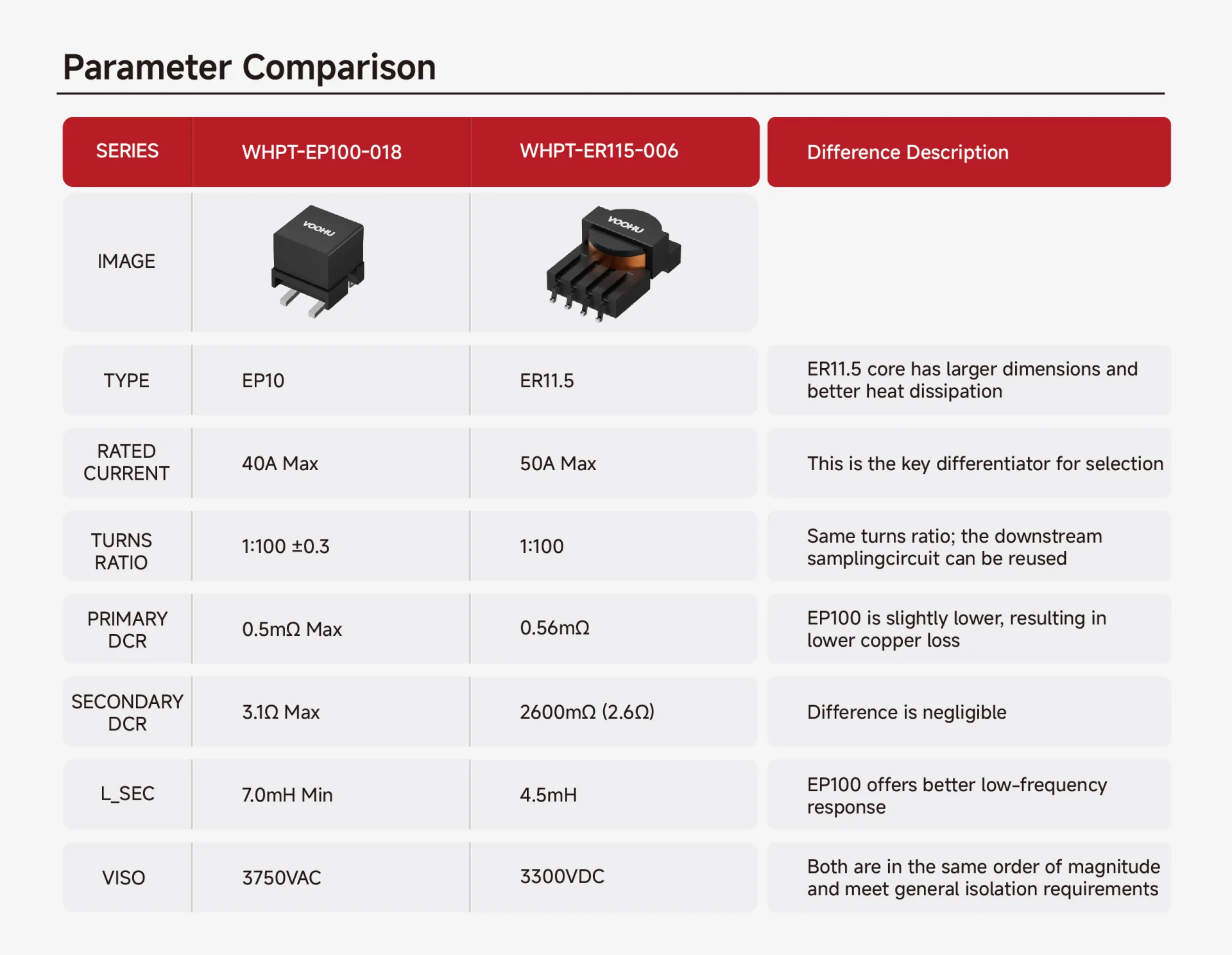
Does 50A peak actually exceed 40A?
A lot of engineers instinctively think, “50 > 40, so it’s over.” But we need to distinguish between peak and RMS—RMS is what drives heating.
For a continuous sine wave, RMS = peak ÷ √2.
50A peak ÷ 1.414 ≈ 35.4A RMS
So this isn’t a “50 versus 40” question—it’s a “35.4A RMS” that falls between the 30A and 40A test points. In terms of heating magnitude, this condition doesn’t exceed the 40A rating.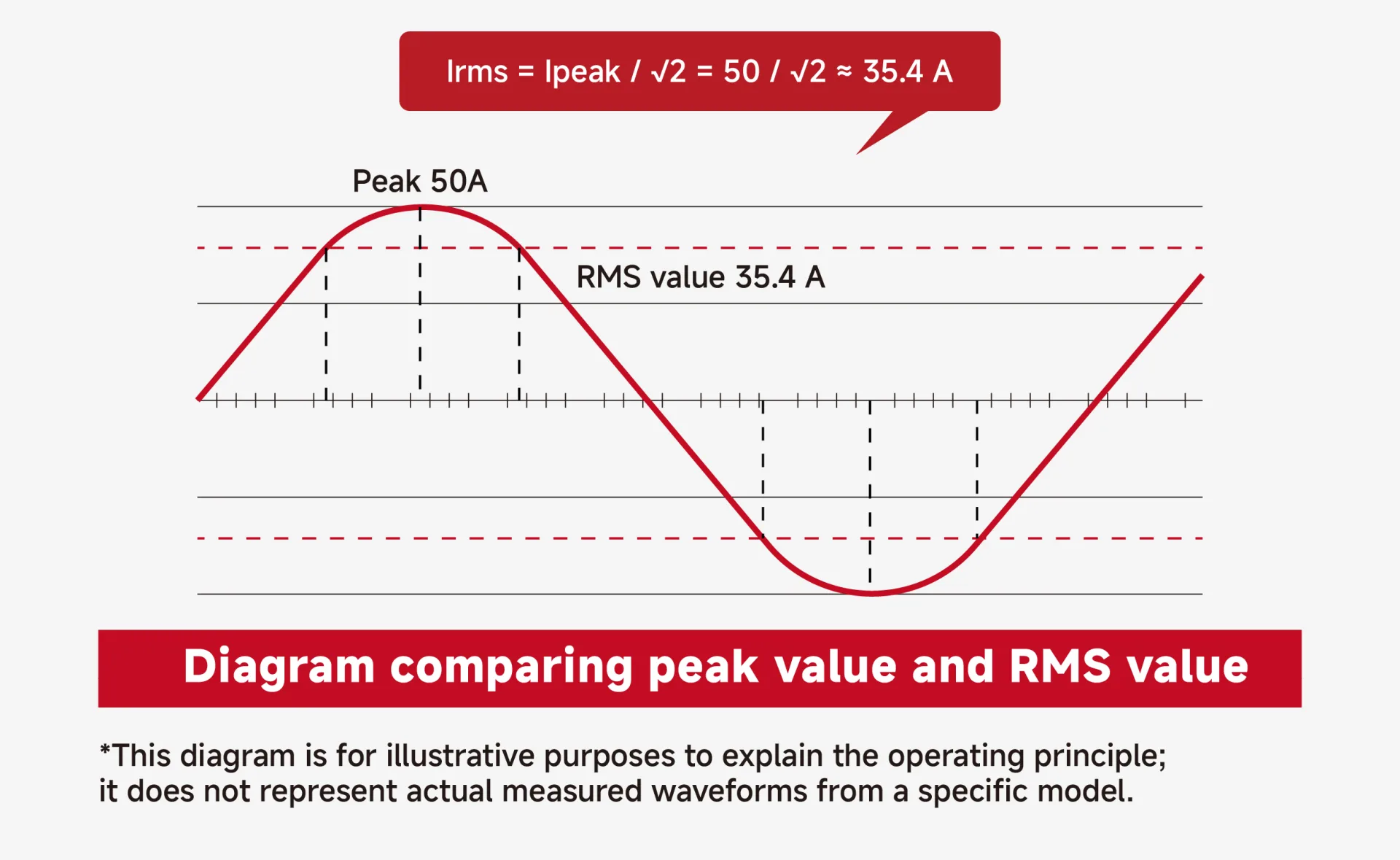
What about temperature rise?
We pulled the thermal test data for this part:
Test ambient: ~25°C, initial product temperature: 25.4°C
| Load Current | Stabilized Temperature | Temperature Rise |
|---|---|---|
| 30A RMS | 52.4°C | 27.0°C |
| 40A RMS | 75.5°C | 50.1°C |
Temperature rise is calculated as stabilized temperature minus initial temperature—not ambient. So 52.4°C minus 25.4°C gives 27°C.
The customer’s 35.4A RMS sits right between 30A and 40A, so these data points serve as a rough reference. But that’s only a paper estimate.
At 90kHz, AC winding losses, core losses, the burden resistor value, PCB heat dissipation, and enclosure airflow all significantly affect the final temperature. Paper calculations give you a direction, but you really need to run it on the actual board.
Advice: Test this part under real operating conditions until thermal equilibrium, then measure the temperature. Don’t make the final call based solely on the datasheet.
Will the core saturate?
This is where many engineers get confused. 40A Max is the rated current—not the saturation current.
Saturation isn’t about the primary current magnitude alone—it’s about whether the flux density stays within limits. Flux density depends on:
-
Total secondary induced voltage (not just the voltage across the burden resistor)
-
Operating frequency (90kHz)
-
Number of turns (100)
-
Effective core cross-sectional area (Ae ≈ 10.7mm²)
For the WHPT-EP100-018 at 90kHz, every 1V RMS increase in total secondary induced voltage raises the peak flux density by about 2.34mT. The datasheet gives a typical Bmax reference of 220mT.
How to tell if the core is saturating:
-
Calculate Bpk based on the actual total secondary induced voltage; keep it below 220mT with margin.
-
Check the output waveform—look for amplitude compression, local flattening, or distortion that might indicate saturation.
-
Verify that the output amplitude stays linear with primary current.
If all three conditions are met, you can conclude the core isn’t saturating under those conditions.
Final selection recommendation
Looking at the whole picture, the WHPT-EP100-018 could “just barely” handle the thermal side, but from a product rating and long-term reliability standpoint, we recommended that the customer switch directly to the WHPT-ER115-006.
Three reasons:
-
Current rating matches directly. The WHPT-ER115-006 is rated 50A Max—no ambiguity about whether it’s “over” or not.
-
Same turns ratio, no secondary-side redesign. Both are 1:100, so the existing sampling circuit and scaling logic can be reused.
-
Frequency coverage is solid. The series covers 20kHz to 1MHz, so 90kHz is well within its comfort zone.
For this project, we suggested the following verification steps:
-
Use actual 90kHz, 50A peak sinusoidal current.
-
Connect the real burden resistor, rectifier, and clamping circuitry.
-
Run it inside the target PCB and enclosure until thermal stability is reached.
-
Record the maximum product temperature and temperature rise.
-
Measure total secondary induced voltage and calculate flux density.
-
Check output scaling, amplitude, and waveform integrity.
If you run into similar questions during current-transformer selection, feel free to reach out to the VOOHU technical support team—we talk shop, engineer to engineer.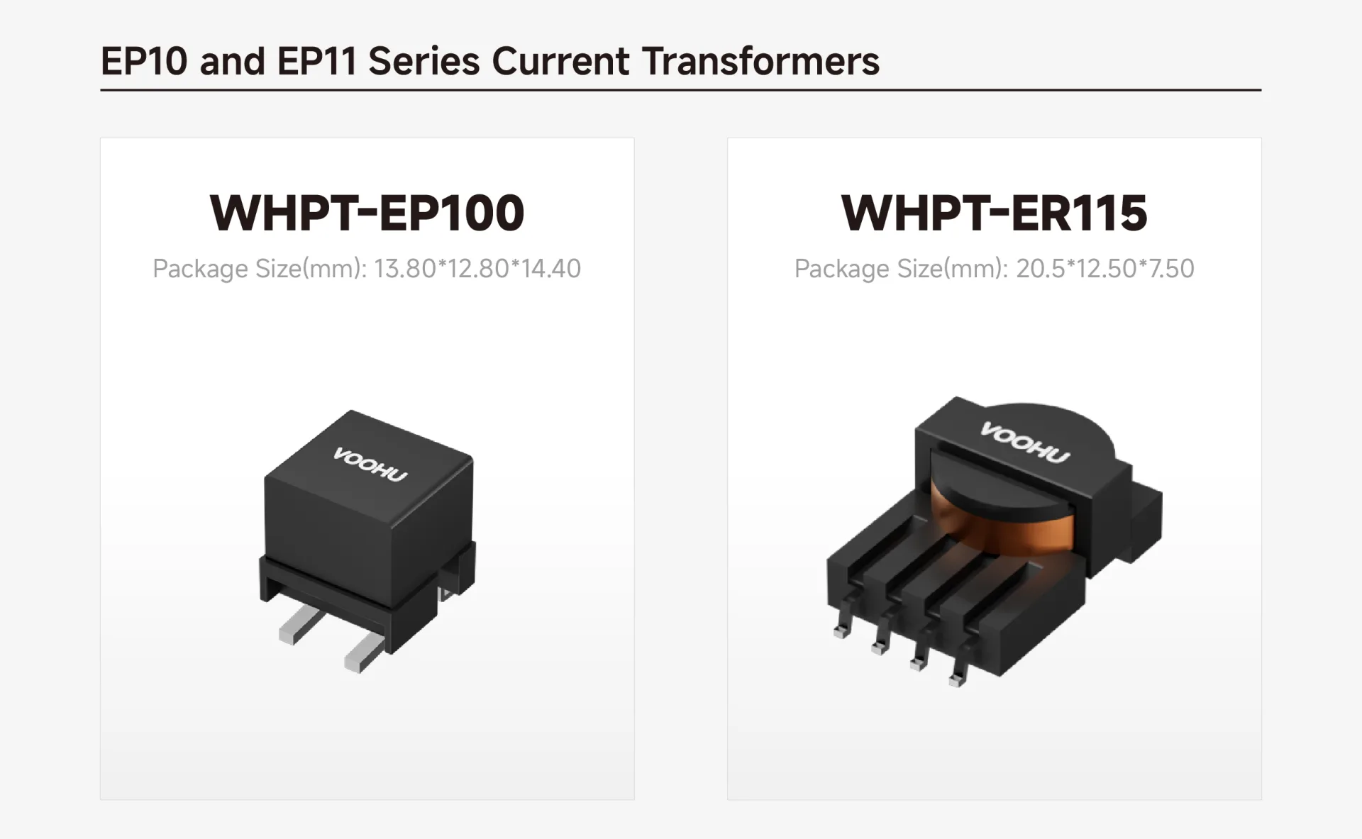
Selection and solution support
VOOHU offers a complete current-transformer portfolio—covering EP7, EP10, ER11.5, EF12.6, EE5, and other core sizes, with primary current ratings from 5A to 50A and turns ratios from 1:20 to 1:200. We also supply matching burden resistors, TVS/ESD protection devices, push-pull transformers, and other peripheral components—so you can build a complete signal chain and isolation solution around current sensing.
Frequently Asked Questions
Q: Can a VOOHU WHPT-series 40A-rated current transformer actually measure 50A peak current?
A: You can’t decide just by comparing “50 > 40”—the waveform type matters first.
For a continuous pure sine wave with no DC bias, 50A peak corresponds to about 35.4A RMS (50 ÷ √2), which is below the 40A RMS rating—so from an RMS heating standpoint, it doesn’t exceed the rating. For other waveforms, recalculate RMS based on the shape and duty cycle; standard current transformers are not suitable for continuous DC detection.
Q: What does the “40A rating” on a current transformer datasheet actually mean? Does exceeding it cause immediate failure?
A: The rating is a design boundary, not a hard “exceed = fail” threshold.
“40A Max” usually implies two things:
-
Thermal limit: At 40A RMS, temperature rise stays within the design allowance (typically 40–50°C).
-
Magnetic limit: At 40A peak, the core won’t saturate.
Exceeding 40A doesn’t necessarily cause immediate damage, but it may lead to:
-
Excessive temperature rise, reducing long-term life.
-
Core entering nonlinear region, distorting the output waveform.
-
Reduced accuracy and increased measurement error.
Q: How do you determine if the core is saturating? Is checking the current magnitude enough?
A: No. Saturation must be evaluated by combining frequency, turns, core area, and total secondary induced voltage.
![[FAQ] Three FAQs for integrated RJ45 (Mag-Jack) application](/upload/image/20260724/fd7e9c7a96b2d92065dbdd6aff0b38b3.jpg)




