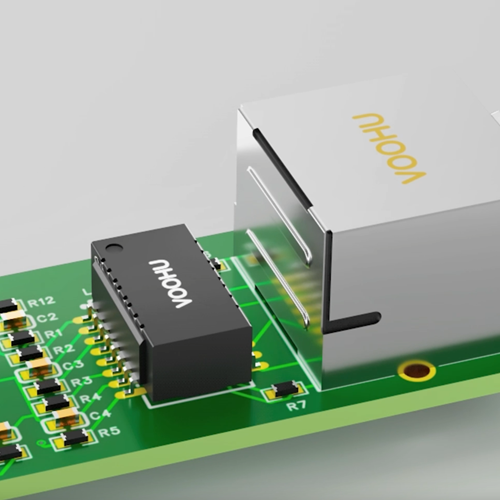
How to Reduce Planar Transformer Temperature Rise: Copper, Core and 60–120 W Selection | VOOHU
How to Reduce Planar Transformer Temperature Rise: Copper, Core and 60–120 W Selection | VOOHU
How can excessive planar transformer temperature rise be reduced? Do not begin by assuming that the transformer is simply undersized. In a high-frequency DC-DC converter, winding current, switching frequency, flux swing, rectification, PCB copper and airflow all affect temperature. The effective remedy depends on whether the dominant heat originates in the windings, the core or neighboring power components.
VOOHU planar transformers cover 60 W, 71 W, 90 W and 120 W families with 3.3 V, 5 V, 12 V and 24 V output configurations. Four 24 V products are used below to show how output current, loss and cooling should be considered together.
1. Locate the heat source before changing the transformer
A strong load-current dependency points first to winding loss
Planar windings have finite resistance. As load rises, RMS current in the primary and secondary increases and DC copper loss grows with current squared. At high frequency, skin effect, proximity effect and unequal current sharing among parallel copper layers add AC loss. If temperature is acceptable at light load but rises quickly near full load, inspect RMS current, layer sharing, solder joints and the synchronous-rectifier path before relying on the power label alone.
Heat at light load or sensitivity to frequency points toward the core
Core loss depends on switching frequency, flux swing, material and temperature. Changes in input voltage, effective on-time, primary turns or control mode change the magnetic operating point. When the transformer remains hot at light load, or its temperature moves significantly with frequency, burst mode or dead time, examine primary voltage, current and drive waveforms for excessive flux swing, volt-second imbalance or unintended DC bias.
A hot spot near the switches may be heat conducted from elsewhere
A planar structure couples thermally to the PCB. This improves heat spreading, but also allows synchronous rectifiers, primary switches, bus copper and nearby inductors to warm the transformer. Record temperatures at the core center, winding terminals, PCB underside and adjacent power devices. A single surface reading cannot reliably identify the source.
2. Reduce winding loss through RMS current and current-path control
DC resistance alone does not predict planar transformer copper loss. Switching current includes ripple and harmonics, so heating follows the RMS value of the complete waveform. Capture primary and secondary currents at nominal and worst-case input. Then check whether parallel layers, copper thickness, vias and terminals distribute current evenly. A local bottleneck can overheat even when the total copper area appears generous.
Thicker copper and parallel layers can reduce DC resistance, but they do not always reduce high-frequency resistance in direct proportion. Interleaving can improve coupling and reduce leakage inductance while increasing interwinding capacitance. A useful design balances efficiency, temperature rise, leakage and common-mode behavior instead of optimizing one parameter in isolation.
3. Check core loss with frequency, volt-seconds and waveform together
For abnormal core temperature, record actual switching frequency and effective on-time at minimum input, maximum input, light load and full load. Startup, burst and transition behavior also matter because they may differ from steady-state calculations. Primary voltage plateaus, magnetizing-current slope and symmetry between half cycles help determine whether the core resets as intended.
Raising frequency can shrink magnetics but usually increases core and AC winding loss. Lowering frequency can increase flux swing. Any frequency change must therefore be reviewed together with turns, material, input range and loop behavior. If ringing is present, identify whether leakage inductance, parasitic capacitance or the commutation loop is responsible before changing frequency to hide the symptom.
4. Build a continuous thermal path without crossing isolation
Planar magnetics can spread heat through pads, copper and nearby PCB regions. Provide adequate copper and vias toward cooler areas, and direct airflow across the core and terminals. Thermal copper and vias must not bridge the primary-to-secondary isolation boundary or compromise creepage, clearance and high-frequency return paths. A heat spreader or chassis interface also needs verified insulation, mounting pressure and long-term reliability.
Airflow, inlet temperature and component spacing directly affect the final temperature. Test sealed equipment in its real enclosure and orientation. Forced-air designs should include the intended reduced-airflow or fan-fault conditions. Before selecting a higher-power transformer, confirm that heat can leave the PCB; otherwise the same region may remain the system hot spot.
5. A fast troubleshooting sequence for planar transformer temperature rise
Compare no-load, light-load and full-load temperature first
With input voltage, switching frequency, airflow and ambient temperature held constant, record temperature at no load, light load and full load. A steep rise with load points first to RMS current, copper-layer sharing and connections. Persistent heating at light load shifts attention to the core operating point, control mode and drive waveform. A hot spot that remains close to a rectifier or switch may instead be receiving heat from that neighboring component.
Then observe the response to frequency, airflow and component spacing
Change switching frequency, airflow or component spacing separately while keeping the other conditions fixed. Record the core center, winding terminals, PCB underside and nearby power-device temperatures. Strong frequency sensitivity calls for a closer check of flux swing and core loss; a clear improvement with airflow indicates that the airflow or heat-spreading path needs attention. This sequence helps the prototype team focus on the most likely source before changing hardware.
6. Four VOOHU 24 V planar transformer choices from 60 W to 120 W
Each product below provides a 24 V output direction and can serve as a starting point based on output current and power. Their inductance values are not identical, so they must not be treated as simple power-scaled substitutes. Topology, input range, switching frequency, pinout and the complete specification must still match the converter.
| 24 V design direction | VOOHU product | Key specifications and selection direction |
|---|---|---|
| About 60 W, 24 V / 2.4 A | WHPT-EQ200-014 | 60 W; 21 μH; 0.5 μH maximum leakage; 1:1:0.5 turns ratio; Iast 6 A; 24 V / 2.4 A output. A useful lower-power baseline for efficiency and thermal testing. |
| About 71 W, 24 V / 2.9 A | WHPT-EQ200-018 | 71 W; 18 μH; 0.5 μH maximum leakage; 1:1:0.5 turns ratio; Iast 6.6 A; 24 V / 2.9 A output. For designs requiring more output current while retaining a low-profile approach. |
| About 90 W, 24 V / 3.7 A | WHPT-EQ200-022 | 90 W; 280 μH; 0.5 μH maximum leakage; 1:1:0.5 turns ratio; 24 V / 3.7 A output. Match topology, frequency, input range and thermal target before selection. |
| About 120 W, 24 V / 5 A | WHPT-EQ200-026 | 120 W; 280 μH; 0.5 μH maximum leakage; 1:1:0.5 turns ratio; 24 V / 5 A output. A higher-current direction that also needs planned copper, vias, rectification and airflow. |
Do not choose output current by matching the continuous load to an identical catalog number. Include transient current, ambient temperature, input range, efficiency target and cooling margin. Providing these conditions to VOOHU makes it easier to decide whether the first prototype should begin with the 60 W, 71 W, 90 W or 120 W family.
7. Compare prototypes under fixed thermal conditions
Establish one repeatable measurement baseline
Fix input voltage, output load, switching frequency, control mode, ambient temperature, airflow and measurement points. Log temperature until it approaches steady state while recording input power, output power and critical current waveforms. Thermal imaging is valuable for locating hot spots; quantitative comparisons require consistent emissivity and viewing angle, with suitable contact measurement used to confirm key points.
Cover worst-case input, load and ambient temperature
Test minimum and maximum input, light load, half load, full load, startup and load transients, then repeat the critical points at the target hot ambient. If the controller changes mode at light load, capture both sides of the transition. The pattern reveals whether heating follows current, frequency or a short operating event.
Change one variable at a time
After adjusting copper, parallel layers, switching frequency, airflow or component placement, repeat the test with all other conditions fixed. Changing the transformer, rectifier and heat spreader together may reduce temperature without revealing which measure worked. Recheck efficiency, ripple, switch stress, EMI and isolation so that the thermal fix does not create a new problem.
8. Frequently Asked Questions (FAQ)
1. Should a hot planar transformer simply be replaced by a higher-power part?
Not immediately. Determine whether winding loss, core loss or external heating dominates, then match topology, turns ratio, inductance, pinout and frequency. A higher-power product helps only when the electrical conditions and thermal path also fit.
2. What surface temperature is acceptable for a planar transformer?
There is no universal value independent of ambient temperature, insulation system, measurement location and equipment requirements. Use the applicable product and system limits, and judge the stabilized hot spot rather than a brief case reading.
3. Why can a planar transformer run hot at light load?
Copper loss decreases at light load, but the core still sees switching excitation. The controller may also enter burst, skip or variable-frequency operation. Check actual frequency, primary volt-seconds and magnetizing current to separate core loss, bias and conducted heat from nearby components.
4. Does thicker PCB copper always reduce temperature rise?
No. Thicker copper reduces DC resistance and can spread heat, but high-frequency resistance still depends on skin and proximity effects, and current may not share equally among layers. Copper thickness, layer count, vias and winding structure must be considered together.
5. How can the four 60 W to 120 W products be shortlisted quickly?
Start with output voltage and continuous current, then provide input range, topology, switching frequency, ambient temperature, cooling method and space limits. VOOHU can use those conditions to help match inductance, turns ratio, pinout and a sample plan.
9. Conclusion: evaluate loss and cooling in the same selection table
Reducing planar transformer temperature rise requires two answers: where the loss is generated and where the heat can flow. Separate winding, core and external heat by observing load, frequency and temperature behavior, then address copper paths, switching waveforms and airflow. WHPT-EQ200-014, WHPT-EQ200-018, WHPT-EQ200-022 and WHPT-EQ200-026 cover 24 V / 2.4 A through 24 V / 5 A directions. For a closer match, request samples and selection support from VOOHU and validate the candidate in the target converter and thermal environment.