How to Choose a Dual-Port LAN Transformer: 48/50 Pins, DIP/SMT and Concurrent PoE Validation | VOOHU
How to Choose a Dual-Port LAN Transformer: 48/50 Pins, DIP/SMT and Concurrent PoE Validation | VOOHU
How should a dual-port LAN transformer be selected? When a switch, industrial gateway or controller places two Gigabit copper ports on one board, a dual-port device can consolidate the magnetic channels and reduce the number of packages. “Dual port,” however, describes the package architecture only. Data rate, pinout, mounting style, PoE capability and operating temperature still need to match the design.
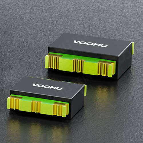
VOOHU offers 100/1000BASE-T LAN transformers in single- and dual-port, SMT and DIP, non-PoE and PoE configurations. The three dual-port Gigabit products below illustrate how to choose among 48 or 50 pins, assembly methods and simultaneous two-port operating conditions.
1. Start with the way both ports will operate
A dual-port LAN transformer does not make two RJ45 ports share one winding set. It contains two port channels in one package. Each Gigabit port still carries four differential pairs from its PHY interface, through the magnetics and onward to its own RJ45. Port A and Port B, their polarity and their center taps must remain identifiable in the schematic and PCB. A swapped port order or an incorrect center-tap connection may escape a continuity check yet fail during link training, PoE operation or EMC testing.
Define the board architecture first. Are both connectors adjacent? Does one dual-port PHY serve them? Will both links run continuously at full rate? Will they both carry PoE? A dual-port package is attractive when the PHY and two RJ45 connectors are grouped together. Separate single-port parts can be easier when the connectors are far apart. Port count is therefore a layout decision as well as a BOM decision.
2. A 48-pin and a 50-pin part are not interchangeable by number
A 48-pin dual-port transformer: verify DIP holes and port order
A 48-pin dual-port LAN transformer is often offered in a DIP package, but equal pin counts do not guarantee equal pin functions. Starting at Pin 1, map the PHY-side pairs, cable-side pairs and center taps for Port A and Port B. The through-hole pattern also consumes space on both sides of the PCB, so hole diameter, pitch, insertion orientation and wave-soldering requirements must be defined before layout release.
A 50-pin dual-port transformer: compact SMT routing needs disciplined fan-out
A 50-pin dual-port LAN transformer commonly supports a compact SMT layout. A 1.02-mm pitch avoids through holes, while placing two sets of differential pairs, center taps and any PoE copper around one package. Keep the two port groups distinct, avoid unnecessary crossovers and preserve pair symmetry near the component. Another 50-pin device is not automatically pin compatible; use its pin table and recommended land pattern.
Choose DIP or SMT together with the assembly process
DIP supports through-hole retention and wave soldering, while SMT fits reflow assembly and dense automated placement. Neither is inherently superior for every design. Compare top- and bottom-side space, component height, trace escape, repair access and the production line. Changing from DIP to SMT—or from 48 to 50 pins—requires a new library check and board validation.
3. Validate a dual-port PoE transformer with both ports loaded
A dual-port PoE LAN transformer carries two Gigabit signal paths and DC current through the applicable center-tap routes. A PoE label is a useful selection boundary, but it is not a direct statement of total system power. PSE or PD role, current per pair, cable drop, winding DCR, ambient temperature and PCB copper all affect thermal performance.
Do not stop after one port links over a short cable at room temperature. Establish both links, apply the intended traffic and powering condition, and monitor negotiation, error counters, package temperature and recovery after a hot restart. If the two ports have different loads, swap them and repeat the test to reveal asymmetry in copper area, airflow or connector position. A non-PoE product must not be placed into an energized center-tap path merely because its pin count looks similar.
4. Three VOOHU dual-port Gigabit LAN transformer options
All three products below target dual-port 100/1000BASE-T designs. Their useful distinctions are DIP or SMT mounting, 48 or 50 pins, temperature range and PoE capability. Other isolation, temperature and power options are available in the same VOOHU product family when a project falls outside these branches.
| Design direction | VOOHU product | Selection points |
|---|---|---|
| Dual Gigabit, through-hole, non-PoE | WHDG48201-1G | Dual port; 100/1000BASE-T; DIP; 48 pins; 2.0-mm pitch; 0 to 70 °C; 1500 Vrms; non-PoE. Suited to boards with an established through-hole process. |
| Dual Gigabit, SMT, non-PoE | WHSG50009G | Dual port; 100/1000BASE-T; SMT; 50 pins; 1.02-mm pitch; 0 to 70 °C; 1500 Vrms; non-PoE. A compact option for adjacent non-powered ports. |
| Dual Gigabit, SMT, PoE+ | WHSG50011PG | Dual port; 100/1000BASE-T; SMT; 50 pins; 1.02-mm pitch; -40 to +85 °C; 1500 Vrms; PoE+ up to 720 mA. A wide-temperature PoE branch. |
WHDG48201-1G and WHSG50009G separate the DIP and SMT assembly paths. WHSG50009G and WHSG50011PG are both 50-pin SMT devices, but their temperature and PoE boundaries differ. Eliminate unsuitable mounting and power branches first, then verify the winding diagram, pin table, dimensions and PCB pattern for the exact product.
5. Complete three checks before the BOM is released
Match the schematic and footprint pin by pin
Create a separate net list for each port, covering PHY side, RJ45 side, polarity, center taps and no-connect pins. Schematic pin numbers, PCB pad numbers and the physical Pin 1 orientation must agree. When changing products, rebuild the mapping from the current documents rather than carrying over a similar-looking footprint.
Run traffic on both ports and watch for interaction
Begin with known-good PHY, RJ45 and cable paths. Run Port A and Port B individually, then operate both together. Compare negotiated speed, error counters, sustained traffic and cold or hot restart behavior. A fault that appears only with both ports active points toward power integrity, reference-plane discontinuity, inter-port coupling or local heating.
Combine PoE load with the worst intended temperature
For a PoE design, use the intended PSE or PD circuit, cable and load. Operate both ports under the planned power condition at the highest specified ambient temperature. After temperatures stabilize, recheck the links and restart behavior. Designs with a low-temperature requirement should also verify link-up and power delivery at that lower limit.
6. Frequently Asked Questions (FAQ): choosing dual-port LAN magnetics
1. Does one dual-port transformer always use less board area than two single-port products?
No. It is often compact when the two RJ45 connectors and PHY channels are grouped together. When the ports are separated, two single-port devices may avoid long differential routes. Compare the complete layout, including fan-out, isolation area, PoE copper and repair clearance.
2. Can a 48-pin and a 50-pin dual-port Gigabit transformer be interchanged?
Not by port count and speed alone. Pin count, mounting method, pitch, port order, center-tap arrangement and footprint can differ. Even two 50-pin products require pinout and land-pattern checks for the exact suffix.
3. Does a 720-mA label on dual-port PoE magnetics describe a shared total?
Do not interpret “up to 720 mA” as a fixed system total or allocation without the applicable product conditions. Match the documented test condition, PSE or PD topology and current per pair, then confirm thermal and link stability with both ports loaded.
4. Is an SMT dual-port transformer automatically better for high-speed signals than a DIP part?
Mounting style alone does not define signal performance. The exact product sets the supported data rate and electrical characteristics, while PCB routing and reference planes also matter. Choose SMT or DIP for assembly and layout, then verify the complete channel with the target PHY and cables.
5. What information helps VOOHU recommend a product for a dual-port board?
Provide the PHY part number and reference circuit, RJ45 locations, PoE requirement, operating temperature, mounting preference, isolation target and available space. These details quickly narrow the choice among 48-pin DIP, 50-pin SMT and different PoE configurations.
7. Conclusion: qualify the package with both ports active
A dual-port LAN transformer should be selected around port placement, assembly method and powering role before 48/50-pin mapping, temperature and isolation are finalized. WHDG48201-1G, WHSG50009G and WHSG50011PG cover DIP non-PoE, SMT non-PoE and SMT PoE+ directions. Once a candidate is chosen, request samples and selection support from VOOHU and validate it with the intended PHY, RJ45 connectors, cables and simultaneous two-port workload.