


VOOHU :Voltage-Mode vs Current-Mode PHY: Drive Principles, Peripheral Design, and Selection Guide
The driver type of an Ethernet PHY chip directly determines system signal integrity, anti-interference capability, and hardware design complexity. Voltage-mode and current-mode PHYs may appear to differ only in signal carrier, but they have fundamental differences in internal architecture, biasing mechanism, and peripheral circuitry. Selecting the wrong type will lead to link failure or performance degradation.
For this reason, beyond PHY chip selection, supporting components such as transformers, common-mode chokes, and connectors also determine the success or failure of the link. VOOHU Electronics has deep expertise in physical-layer supporting components and provides verified transformer selection and peripheral reference designs for mainstream PHYs such as Jinglue JL2101C‑NI, enabling a complete Ethernet connection in one step.
More products on this site:Voltage-driven PHY vs. Current-driven PHY: How to correctly connect the network transformer?
1. Fundamental differences in driver principle
Voltage-Mode Driver
Internally equivalent to a voltage source, capable of outputting a defined voltage (e.g., 0V, 3.3V) to represent logic signals. Signal transmission uses voltage amplitude as the carrier, similar to “speaking by volume”. The circuit architecture is simple and low‑cost, but signals are prone to attenuation over long distances.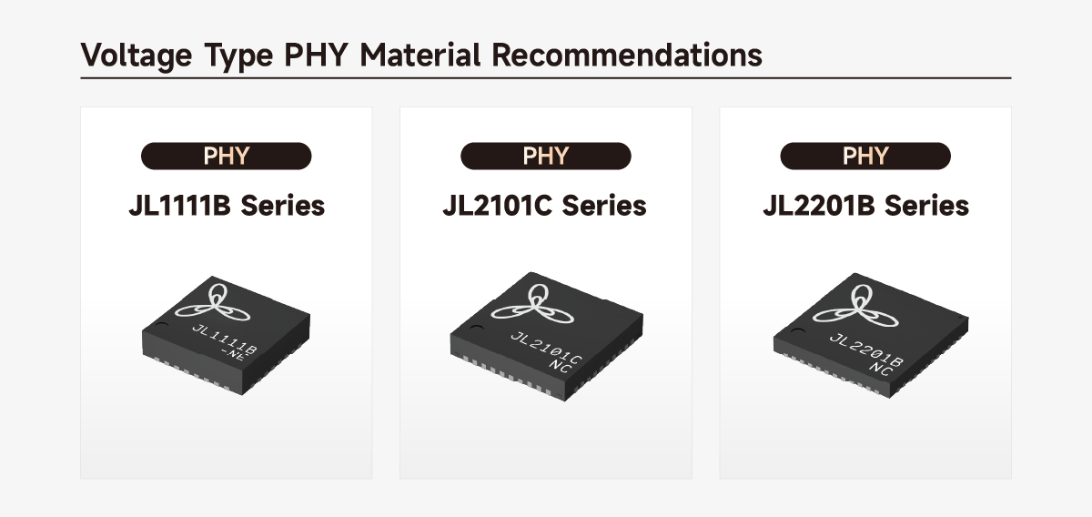
Current-Mode Driver
Internally equivalent to a constant current source, outputting a preset constant current and encoding information via current changes. Requires an external bias voltage and uses termination resistors to convert the current signal into a transmittable voltage signal. Strong anti‑interference capability, suitable for high‑speed, long‑distance, and harsh electromagnetic environments, but requires more complex impedance matching.
2. Internal structure differences
Voltage-mode PHY integrates a voltage driver circuit and internal bias, with low output impedance (50–100Ω). Some models allow driver configuration via registers.
Current-mode PHY uses an open‑drain or current‑mirror structure, with high output impedance (up to kΩ level), relies on an external DC operating point, and demands higher power‑supply noise rejection.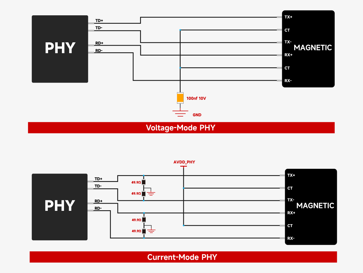
3. Critical role of bias voltage
For a current-mode PHY, the bias voltage is applied through the center tap of the Lan Transformer to provide a stable DC operating point for the internal current driver, ensuring symmetrical swing of the differential current signal and a full signal swing. If the bias is missing or incorrectly connected, the current cannot form an effective loop, the signal amplitude is severely attenuated, and the link cannot be established.
For a voltage-mode PHY, the bias is internal; the center tap only needs AC grounding (blocking DC and passing AC), simplifying peripheral design.
4. Key differences in peripheral circuit design
4.1 Lan Transformer center tap connection
This is the most直观 indicator to distinguish the two types.
-
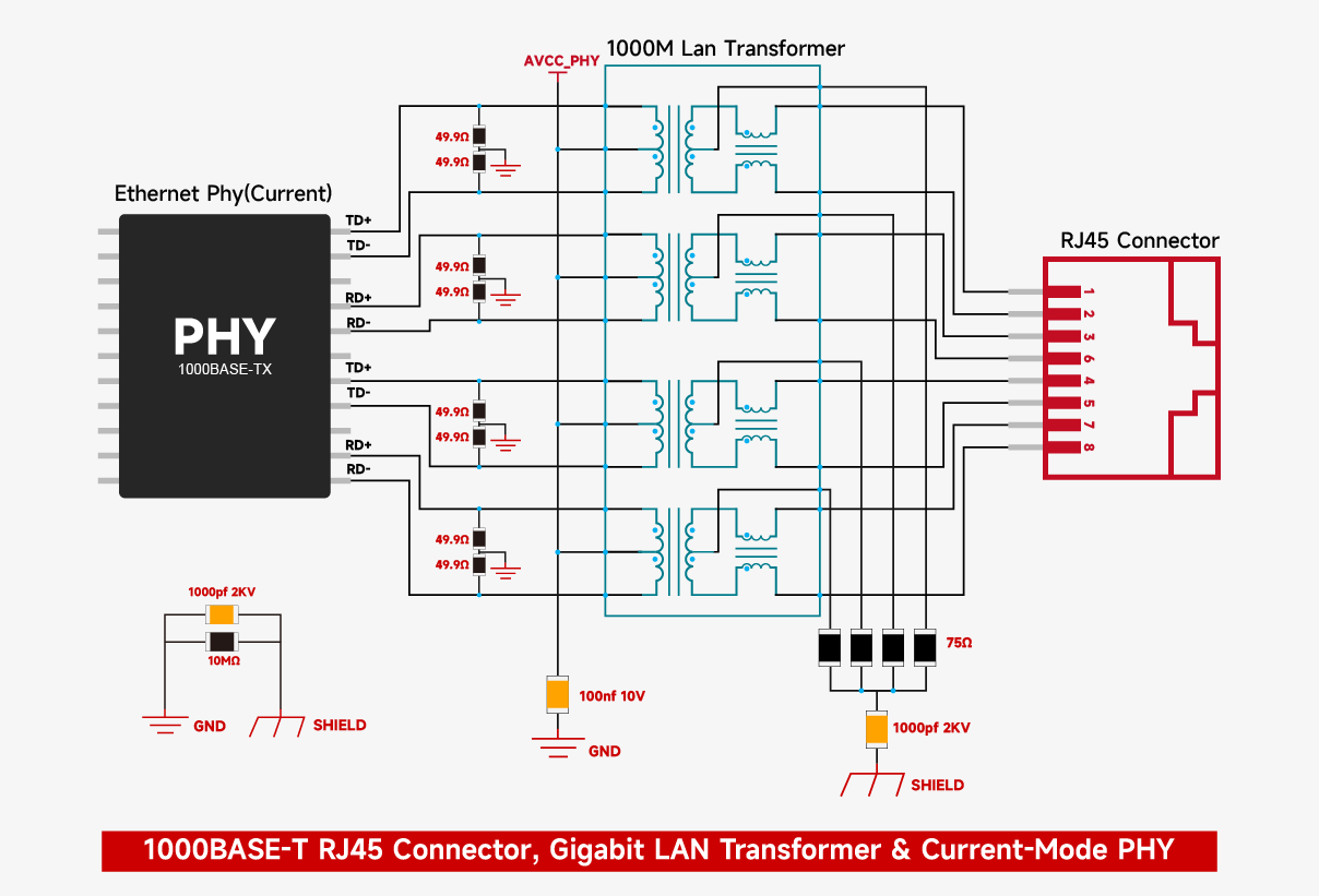
Current-mode: The center tap must be connected to the PHY analog power supply (AVDD/VCC), typically 1.8V, 2.5V, or 3.3V, to establish DC bias for the current source.
-
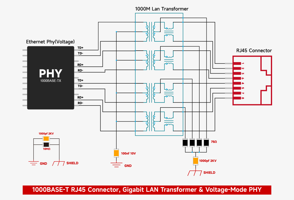
Voltage-mode: The center tap is grounded via a 0.1μF capacitor, forming a high‑frequency low‑impedance path (blocking DC, passing AC).
4.2 Termination matching resistor
-
Current-mode: A 49.9Ω termination resistor must be connected between each differential signal line and ground at the PHY side, placed close to the chip, to convert the current into a voltage signal.
-
Voltage-mode: Usually no external termination resistor is needed because it is integrated inside the chip, but the datasheet must be checked.
4.3 Common‑mode choke placement
-
Current-mode: The common‑mode choke is mandatory on the RJ45 Connector side, close to the cable interface.
-
Voltage-mode: Placement is flexible – it can be on the PHY side or the cable side, offering higher design freedom.
5. Quick methods to identify PHY type
-
Check the “Magnetic Interface” or “Recommended Schematic” section in the datasheet; look for explicit “Voltage Mode” or “Current Mode” labeling.
-
Observe the reference design: center tap connected to power → current‑mode; center tap connected via capacitor to ground → voltage‑mode.
-
Measure output waveform with an oscilloscope: voltage‑mode shows constant voltage amplitude; current‑mode shows current pulse characteristics.
6. Mainstream international part numbers
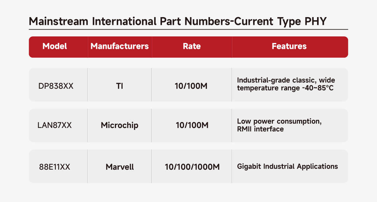
Current‑mode PHYs
Current‑mode PHYs are widely used in industrial Ethernet interfaces due to their strong drive capability and stable anti‑interference performance.Texas Instruments (TI) DP838xx series – a classic in 10/100M, supports -40~85°C wide temperature, proven in industrial controls such as PLCs and drives.Microchip LAN87xx series – also 10/100M, low power, RMII interface simplifies design, suitable for power‑sensitive embedded devices.For Gigabit, Marvell 88E11xx series provides a reliable Gigabit industrial solution, performing well in switches and industrial cameras.
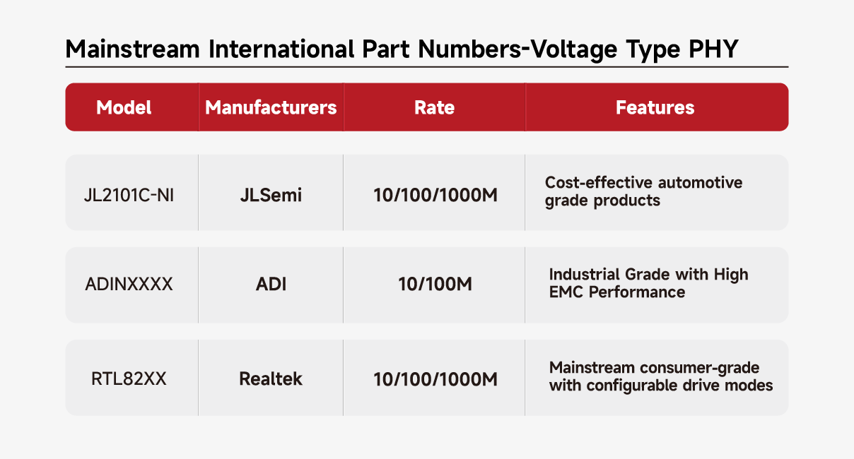
Voltage‑mode PHYs
Voltage‑mode PHYs feature simpler peripheral circuits and flexible voltage adaptation.
-
Local Chinese brand JLSemi Semiconductor JL2101C‑NI – a high‑cost‑performance Gigabit PHY, supports 10/100/1000M auto‑negotiation, with an automotive‑grade version available, suitable for in‑vehicle and security applications.
-
Analog Devices (ADI) ADINxxxx series – 10/100M industrial applications, excellent EMC performance maintains a stable link in strong EMI environments.Realtek RTL82xx series – mainstream choice for consumer and light industrial applications, supports 10/100/1000M, its configurable drive mode can flexibly match different types of Lan Transformers, simplifying hardware debugging.
7. Application scenario suitability
Voltage-mode PHY – due to its simple architecture and cost advantage, dominates consumer electronics, general network equipment, short‑distance PCB routing, and is the first choice for entry‑level designs up to Gigabit.
Current-mode PHY – with excellent anti‑interference and low power consumption, suits industrial automation, automotive Ethernet, PoE‑powered devices, and long‑distance transmission – a reliability guarantee in harsh electromagnetic environments.
8. Key design pitfalls to avoid
-
Never connect the Lan Transformer by experience – always read the datasheet word by word. Incorrect center‑tap connection is the most common cause of failure, manifesting as link failure, extremely short transmission distance, or excessive signal jitter.
-
Current-mode PHY is sensitive to power supply purity – AVDD requires independent filtering.
-
For voltage-mode PHY, pay attention to the center‑tap capacitor value – 0.1μF is typical; for Gigabit, a slightly larger value may reduce jitter.
FAQ
FAQ 1: How can I quickly tell whether a PHY chip is voltage‑mode or current‑mode?
Check the Lan Transformer center‑tap connection in the datasheet: if the center tap is grounded via a capacitor, it is a voltage‑mode PHY; if it is directly connected to a power supply (e.g., AVDD), it is a current‑mode PHY. When VOOHU Electronics provides matching transformers for PHYs such as Jinglue JL2101C‑NI, it also verifies the driver type marking in the datasheet to help customers avoid wrong connections.
FAQ 2: What are the consequences of selecting the wrong PHY type? What is the most common mistake?
The most common consequences are link failure, extremely short transmission distance, or excessive signal jitter. The most common mistake is connecting the Lan Transformer by experience without strictly following the datasheet’s center‑tap connection. VOOHU Electronics often encounters such issues when supporting customer designs – it strongly recommends checking the “Magnetic Interface” section of the datasheet and referring to VOOHU’s verified reference design diagrams.
FAQ 3: Which application scenarios are suitable for voltage‑mode and current‑mode PHYs respectively? How to make a trade‑off during selection?
Voltage‑mode PHYs are suitable for cost‑sensitive scenarios like consumer electronics and short‑distance routing. Current‑mode PHYs are suitable for harsh environments like industrial automation, automotive, and PoE. VOOHU Electronics can directly recommend a complete solution based on the application scenario (e.g., current‑mode PHY with corresponding transformer for industrial field, voltage‑mode PHY for consumer applications), and provide matching Lan Transformers, common‑mode chokes, and RJ45 Connectors to accelerate selection and testing.
From its founding in 2018 to its overseas expansion in 2025, VOOHU Electronics has become a reliable partner for more than 1,000 enterprises by virtue of “excellent quality, fair pricing, attentive service, and reliable delivery.”
If you are also looking for a telecommunications electronic component supplier that saves you worry, money, and effort, why not try VOOHU? After all, the choice of more than 100 listed companies can’t be wrong.
*Choose VOOHU – Truly Reliable. That is not just a slogan; it is an answer written by the trust of 1,000+ customers over eight years.*
Newsletter subscription
Subscribe to our newsletter and stay updated on the latest information of our company and product.
Name
|
I agree that the information that I provide will be used in accordance with the terms of Voohu International Inc. Privacy & Cookies Policy


