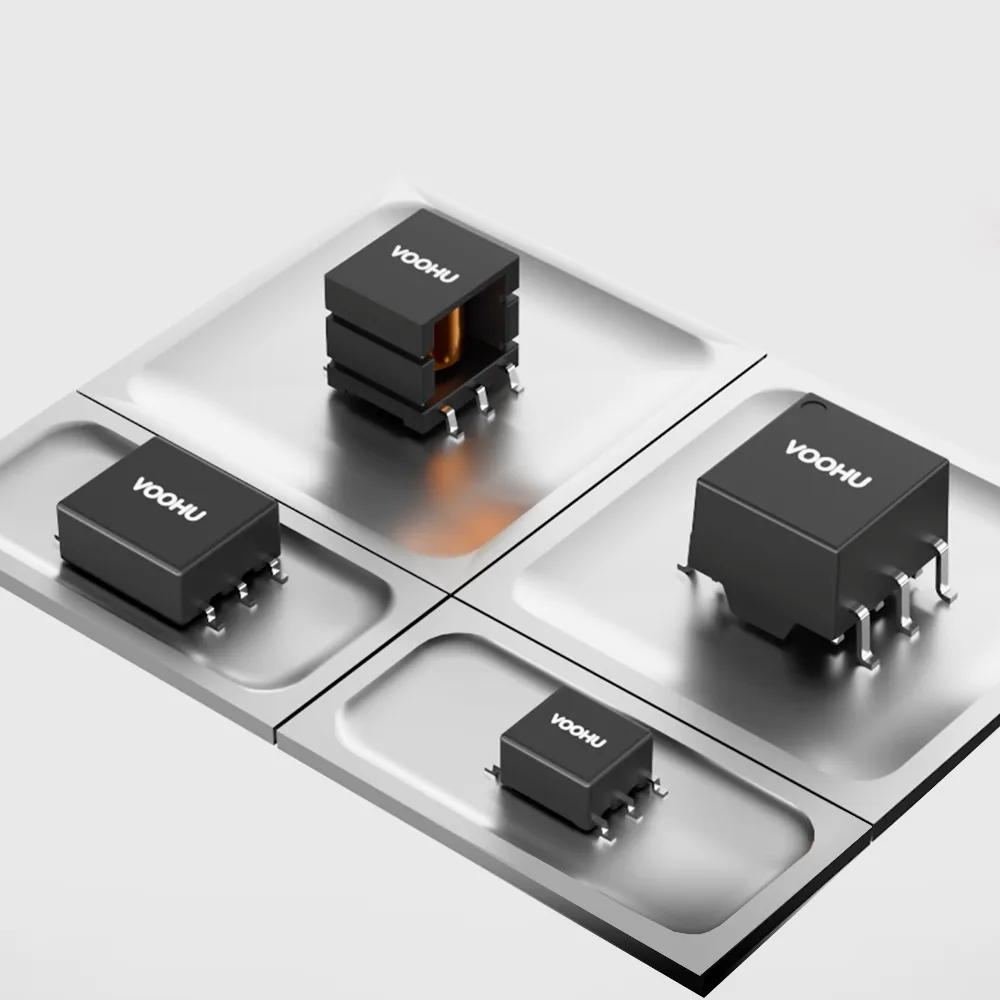
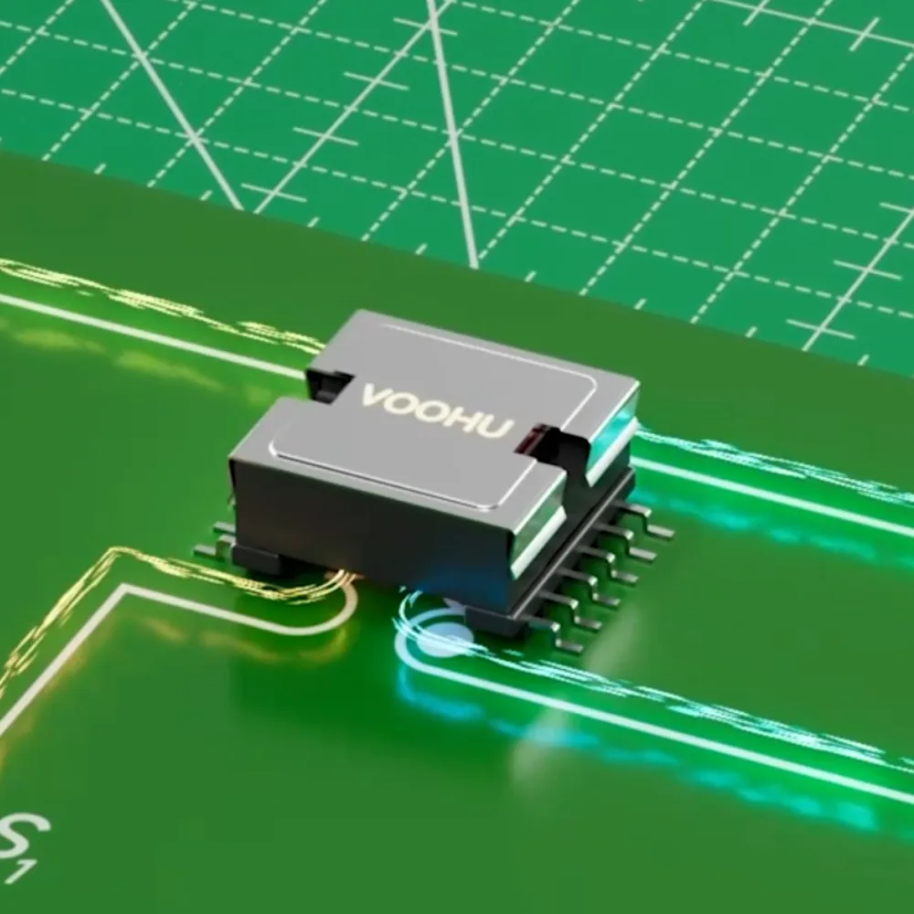
10/100 BASE-TX LAN Transformer Selection Comparison: VOOHU WHSH16109N0 vs. Bothhand NS0013 LF
10/100 BASE-TX LAN Transformer Selection Comparison: VOOHU WHSH16109N0 vs. Bothhand NS0013 LF
1. Competitor Product Overview (Bothhand Enterprise Inc.)
For PC Card, CardBus, and compact 10/100M Ethernet interface designs, Bothhand NS0013 LF uses a 16-pin SMD package with 1CT:1CT TX and RX windings. For an existing-board sourcing change, pin functions and winding polarity need to be checked alongside OCL, frequency-domain requirements, PCB land pattern, and assembly height.
2. VOOHU Replacement Overview (Suzhou VOOHU Electronic Technology Co., Ltd.)
VOOHU WHSH16109N0 is also intended for 10/100 BASE-TX Ethernet interfaces in a 16-pin SMD format. Its RD+/RD−, dual CT, TD+/TD−, RX+/RX−, dual CT, and TX+/TX− functions correspond to the same pin numbers used by NS0013 LF. WHSH16109N0 is therefore a candidate for replacement evaluation, not an assumed drop-in replacement; the PCB footprint, component height, and isolation-test conditions still require verification before release.
3. Key Parameter Comparison
The table includes only items that can be matched by function on both sides. Original frequency ranges, tolerances, and test conditions are retained for selection review and are not a performance ranking.
| Comparison item | Bothhand NS0013 LF | VOOHU WHSH16109N0 |
|---|---|---|
| Product format | 10/100 PC Card LAN magnetics, 16-pin SMD | 10/100 BASE-TX LAN transformer, 16-pin SMD |
| Pin and winding topology | RD+/RD−, dual CT, TD+/TD−; RX+/RX−, dual CT, TX+/TX−; 1CT:1CT for both TX and RX | RD+/RD−, dual CT, TD+/TD−; RX+/RX−, dual CT, TX+/TX−; 1CT:1CT for both TX and RX |
| Turns ratio (TX / RX) | 1CT:1CT, ±3% | 1CT:1CT, ±5% |
| Open-circuit inductance (OCL) | 350 µH min @ 100 kHz, 0.1 V (Pins 16-15 / 7-8) | 350 µH min @ 100 kHz, 0.1 V |
| Insertion loss | −1.1 dB max @ 0.3–100 MHz | −1.1 dB max @ 1–100 MHz |
| Return loss | −18 dB min @ 0.3–30 MHz; −15.5 dB min @ 40 MHz; −13.5 dB min @ 50 MHz; −10 dB min @ 60–80 MHz | −18 dB min @ 1–30 MHz; −14.4 dB min @ 40 MHz; −13.1 dB min @ 50 MHz; −12 dB min @ 60–80 MHz |
| Crosstalk | −38 dB min @ 0.3–100 MHz | −30 dB min @ 1–100 MHz |
| Common-mode rejection (DCMR) | −33 dB min @ 0.3–60 MHz; −26 dB min @ 60–100 MHz | −30 dB min @ 1–100 MHz |
| Operating temperature | 0°C to +70°C | 0°C to +70°C |
| Storage temperature | −25°C to +85°C | −40°C to +85°C |
| Component length | 12.70 mm | 12.70 ±0.50 mm |
| Lead pitch | 1.27 mm | 1.27 ±0.10 mm |
| Component height | 2.00 mm | 2.50 mm max |
| Recommended longitudinal land spacing | 10.70 mm | 10.80 mm Typ |
Notes:
- The 16-pin functions and winding polarity can be matched item by item, but component height, recommended longitudinal land spacing, and land dimensions are not identical. Similar pin count, length, or height alone does not establish a pin-to-pin replacement. Overlay the PCB/CAD data, confirm reflow support and assembly clearance, then validate samples.
- Leakage-inductance values do not use equivalent conditions: NS0013 LF is specified at 0.4 µH max without the same frequency-and-voltage combination shown for WHSH16109N0, while WHSH16109N0 is 0.5 µH max at 100 kHz and 0.1 V. These figures should not be treated as a direct performance ranking.
- DCR and isolation withstand voltage also need review against their test pins and acceptance conditions. NS0013 LF states 0.9 Ω max DCR for Pins 16-15 / 7-8 and 1500 Vrms HI-POT; WHSH16109N0 states 1400 mΩ max DCR and 1500 VAC / 1 mA / 60 s isolation. The pin definitions, duration, and current conditions are not fully aligned, so they are not directly comparable.
4. Applications
- Transmit/receive paths between a 10/100M Ethernet PHY and the isolated network side; verify TX/RX, CT, and common-mode-related pin locations and polarity before a sourcing change.
- Existing-board alternates or new design introduction after PCB footprint overlay, reflow assembly, isolation withstand, and system link verification are complete.
5. FAQ
Can WHSH16109N0 be used as a direct replacement for NS0013 LF?
A direct conclusion is not supported. Pin functions and winding topology can be matched, but component height, recommended land pattern, and some test conditions differ. Treat it as a replacement evaluation with PCB/CAD overlay and sample validation.
Both parts specify 350 µH min OCL. Does that mean their electrical performance is identical?
No. The OCL test frequency and voltage can be aligned, while turns-ratio tolerance, insertion-loss coverage, return loss, crosstalk, and common-mode rejection still need review against the target circuit.
Why are leakage inductance, DCR, and isolation values not ranked directly?
Their pins, duration, or test conditions are not fully aligned. Comparing values obtained under different conditions can be misleading; sample testing and the original design requirements remain the final criteria.
What should be verified first when evaluating samples?
Check the PCB land pattern and assembly clearance first, then validate link performance, reflow assembly, and isolation withstand in the target PHY circuit before approving a material change.
Why VOOHU?
One-stop sourcing: connectors + magnetics + interface chips, full support from selection to small-batch production.
Custom solutions: just share your application requirements and budget to get a tailored solution with professional technical support.
Fast development: direct from the manufacturer, rapid FAE response, efficient sampling, shorter time-to-market.
Core qualifications: ISO9001, ISO14001, RoHS, REACH; two in-house factories ensure delivery and quality.
For more information, visit VOOHU: China www.voohu.cn | Overseas www.voohuele.com | Technical support: song.lei@voohu.cn
Replacement Cross-Reference
WHSH16109N0 is a candidate for NS0013 LF replacement evaluation. Final approval requires PCB footprint overlay and sample validation in the target design.