How to Stop Molded Power Inductor Coil Whine: Light-Load PFM, Magnetostriction, IRMS and ISAT Selection | VOOHU
How to Stop Molded Power Inductor Coil Whine: Light-Load PFM, Magnetostriction, IRMS and ISAT Selection | VOOHU
A router, camera, audio unit or compact power module may be quiet at full load yet emit a faint buzz or chirp in standby. This is a common form of DC-DC light-load noise. Learning how to stop molded power inductor coil whine starts with separating the electrical excitation from the mechanical response. PFM or burst operation may create an audible envelope, while magnetostriction, winding force and PCB resonance determine how strongly that excitation is heard.
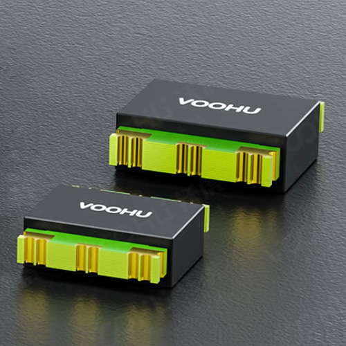
A molded inductor embeds the winding in metal magnetic powder and forms the structure as one body. The winding has less freedom to move than it does in many assembled wire-wound constructions, making molded inductors strong candidates for low-noise rails. That structural advantage is not a promise of silence in every converter. Magnetic material still changes dimension slightly under an alternating field, and the board can amplify vibration when the excitation approaches a mechanical resonance.
1. How to stop molded power inductor coil whine: identify the excitation first
Light-load PFM and burst operation can create an audible envelope
Many buck converters use fixed-frequency PWM at moderate and high load, then enter PFM, pulse skipping or burst mode to reduce switching loss at light load. Individual switching edges may remain above the audible range, but groups of pulses can repeat at hundreds of hertz or a few kilohertz. Inductor current follows that envelope, so magnetic and mechanical forces do as well. The familiar clue is noise that is strongest in standby and disappears after more load is applied.
If the controller supports forced PWM, use it as a controlled comparison on the prototype. A large reduction in sound points to the light-load strategy as the main excitation. The next decision is a system trade-off between acoustic performance and standby efficiency, using only operating modes and thresholds supported by the controller. If the sound barely changes, continue with the inductor operating point and the board mechanics.
Magnetostriction and PCB resonance can amplify a small vibration
Magnetic material changes dimension by a very small amount as flux changes. Larger ripple and irregular current packets produce a stronger periodic force. Molding restrains winding movement but cannot remove the material response itself. When the excitation aligns with a resonance of the component, solder joints, copper area or PCB, a vibration that would otherwise be insignificant becomes audible.
Placement near a board edge, a long slot or a large unsupported area can turn the PCB into an acoustic radiator. Two electrically identical prototypes may sound different because of board thickness, screw location, enclosure contact or solder condition. Coil whine therefore has both an electrical source and a mechanical transmission path.
Use load, mode and source comparisons to narrow the cause
Record how sound changes with input voltage, output load and temperature, then localise it with a near-field microphone or an insulated acoustic probe. Compare fixed PWM with the normal light-load mode, the original inductor with a same-inductance candidate, and the bare board with its intended mounting. Change one condition at a time so control, component and structure effects remain distinguishable. Measurements around mains or high-voltage nodes require suitable isolation and safe probing.
2. IRMS versus ISAT in inductor selection: inductance alone is not enough
ISAT must cover peak current and load transients
ISAT describes the current capability associated with inductance reduction under DC bias. Base the selection on actual peak current and include startup, load-step, input-voltage and current-limit conditions. Operation too close to saturation reduces effective inductance, increases ripple and raises peak current. The larger magnetic-force swing can aggravate acoustic noise while also increasing stress on the switches and output capacitors.
IRMS and DCR set the thermal side of the margin
IRMS addresses continuous-current heating, while DCR contributes directly to copper loss. At the same inductance, lower DCR normally helps temperature rise, but size and available current capability also change. An inductor is not suitable merely because its ISAT is high enough, and an IRMS rating alone says nothing about peak-current saturation. Steady-state temperature and transient magnetic margin must both pass.
A larger inductance can move the noise instead of curing it
More inductance can reduce ripple in some operating conditions, but it can also change loop response, DCR, size and the pattern of light-load pulses. Too little inductance raises ripple and peak current. Keep the value within the regulator's recommended range, calculate ripple at the real input, output and switching frequency, then confirm waveform, efficiency, temperature and transient response. Treating a larger value as a universal noise cure often moves the problem to a different load point.
3. Choosing a VOOHU molded inductor for a low-noise rail
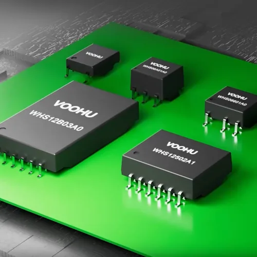
VOOHU molded inductors cover low-profile, compact and higher-current power rails. Start with height and PCB area, compare DCR, IRMS and ISAT at the target inductance, then validate light-load mode, full-load temperature and load transients on the assembled unit. The following three product families provide useful starting points across different size and current ranges.
| Application and primary constraint | VOOHU product family and published range | Selection and acoustic focus |
|---|---|---|
| Ultra-thin equipment and compact point-of-load rails; height and area dominate | WHYTA0412 series: 4.4 × 4.2 × 1.0 mm, 0.15–4.7 μH, DCR 9–195 mΩ, IRMS 1.8–7.5 A, ISAT 2.2–15 A | Lock the 1.0 mm height and target inductance first, then verify peak-current and thermal margin together with the light-load mode |
| Portable electronics, cameras and small communication boards; balanced size and current | WHYTP0320 series: 3.4 × 3.2 × 1.8 mm, 0.33–10 μH, DCR 21–422 mΩ, IRMS 1.4–8 A, ISAT 1.6–10 A | Compare DCR and current margin at the same inductance, with special attention to standby and intermittent-load sound |
| Power modules, servers and networking equipment; temperature and transient margin dominate | WHYT1770 series: 17.15 × 17.15 × 7.0 mm, 2.2–100 μH, DCR 2.5–130 mΩ, IRMS 3.7–29 A, ISAT 5–34 A | Check peak and RMS current separately, then review mechanical coupling between the larger component and the PCB mounting |
These figures are family-level ranges; one individual product does not combine both ends of every range. After fixing the inductance, select the specific product whose dimensions, DCR, IRMS and ISAT jointly provide the required thermal, transient and control-loop margin.
4. A practical path from prototype diagnosis to production validation
Step 1: map the load region in which the sound appears
Increase load gradually from no-load and record where the sound begins, peaks and disappears. Capture inductor current, the switch node and output ripple at the same points. Noise confined to one light-load band calls for a PFM, pulse-skipping or burst-mode check. Sound that rises continuously with current shifts attention toward magnetic operating point, temperature and mechanical resonance.
Step 2: test control strategy and inductor choice separately
First compare forced PWM or another supported light-load setting. Then install a molded-inductor candidate with the same inductance but lower DCR or more current margin. The first comparison tests excitation frequency; the second tests component structure and operating point. Changing both at once may silence the unit, but it removes the evidence needed to reproduce the result in production.
Step 3: review PCB location, soldering and mechanical support
Keep the inductor away from board edges, long slots and large unsupported areas where practical. Maintain symmetric pads and consistent solder volume, and avoid adding an enclosure contact or screw load next to the component. If board mounting changes the sound markedly, optimise component location and PCB support together. Adhesive can affect rework, heat flow and material reliability, so it should not be the first response without a qualified process.
Step 4: close the loop on electrical and reliability performance
After acoustic improvement, repeat minimum and maximum input voltage, no-load to full-load, startup, load-step and temperature tests. Check ripple, efficiency, component temperature, peak current, switch-node overshoot and EMI. A change is production-ready only when acoustic, electrical and reliability results all remain acceptable.
5. Frequently Asked Questions (FAQ)
1. Is a molded power inductor guaranteed to be free of coil whine?
No. Molding reduces winding freedom and improves mechanical stability, but magnetostriction, an audible light-load envelope and PCB resonance can still produce sound. A molded inductor is an important low-noise design choice, not a substitute for checking control mode and board structure.
2. Why does a DC-DC converter whine only at no-load or light load?
The usual reason is a transition into PFM, pulse skipping or burst mode. Groups of switching pulses repeat inside the audible range. As load rises and continuous PWM returns, that envelope changes or disappears. A load sweep and mode comparison can confirm the mechanism.
3. For coil whine, which matters more: IRMS or ISAT?
Both must pass. ISAT supports peak-current and transient magnetic margin; IRMS supports continuous-current temperature rise; DCR influences copper loss. Low-noise selection should include peak current, RMS current, temperature and inductance reduction rather than relying on one rating.
4. Will increasing the inductance eliminate audible noise?
Not necessarily. More inductance may reduce ripple but can increase DCR and alter loop or light-load behaviour. Stay within the regulator's recommended range and use waveform plus acoustic testing instead of assuming that the largest value is the quietest.
5. How should I shortlist the three VOOHU molded-inductor families?
Start with WHYTA0412 when ultra-low height is critical, WHYTP0320 for compact portable rails, and WHYT1770 where a wider inductance and higher-current range is needed. At the target inductance, verify DCR, IRMS, ISAT and dimensions, followed by light-load sound, full-load temperature and transient tests.
6. Conclusion: treat excitation, magnetics and PCB structure as one system
The reliable way to stop molded power inductor coil whine is to identify whether PFM or burst operation creates the audible excitation, verify L, DCR, IRMS and ISAT at the real operating point, and remove PCB resonances that amplify vibration. VOOHU WHYTA, WHYTP and WHYT molded-inductor families cover low-profile, compact and higher-current board-level power needs. A shortlist built from input and output conditions, peak and RMS current, space and acoustic targets—then verified with waveform, temperature and sound measurements—can resolve noise before it becomes a production issue.