VOOHU Selection Guide: Isolated Supply for a PoE Powered Device (PD) and How to Pick the (Flyback) PoE Power Transformer
VOOHU Selection Guide: Isolated Supply for a PoE Powered Device (PD) and How to Pick the (Flyback) PoE Power Transformer
Introduction: Why PoE Powered Devices (PDs) Keep Failing at the "Isolated Supply" Stage
PoE lets a single cable deliver both data and power, and is now standard on security cameras, wireless APs, IP phones, access readers and IoT gateways. When engineers build the PD (Powered Device) side, the RJ45, LAN magnetics and PD controller are usually copied from a reference design; the real sticking point is the next stage — the "isolated DC-DC" that must step the 37-57V PoE bus down to an isolated 12V/5V/3.3V on the board. The heart of that stage is a flyback transformer, exactly what VOOHU's PoE power transformer family targets.
Typical failures: the transformer runs hot, output ripple is high, no-load loss is excessive, hi-pot fails, radiated EMI exceeds limits, or PoE "negotiates then drops out." Nine times out of ten the culprit is not the controller but the flyback transformer — its turns ratio, inductance, core size, isolation and leakage. As 802.3bt (PoE++) pushes single-port PD power to 51W (Type3) and 71W (Type4), choosing a core one size too small leads straight to thermal runaway. This article walks the PoE chain and makes PD isolated-supply and PoE power transformer selection concrete; for the overall architecture see the VOOHU PoE solution.
Technical Analysis: Where the PD Power Chain Actually Breaks
From the RJ45 to the Board: How PD Power Flows
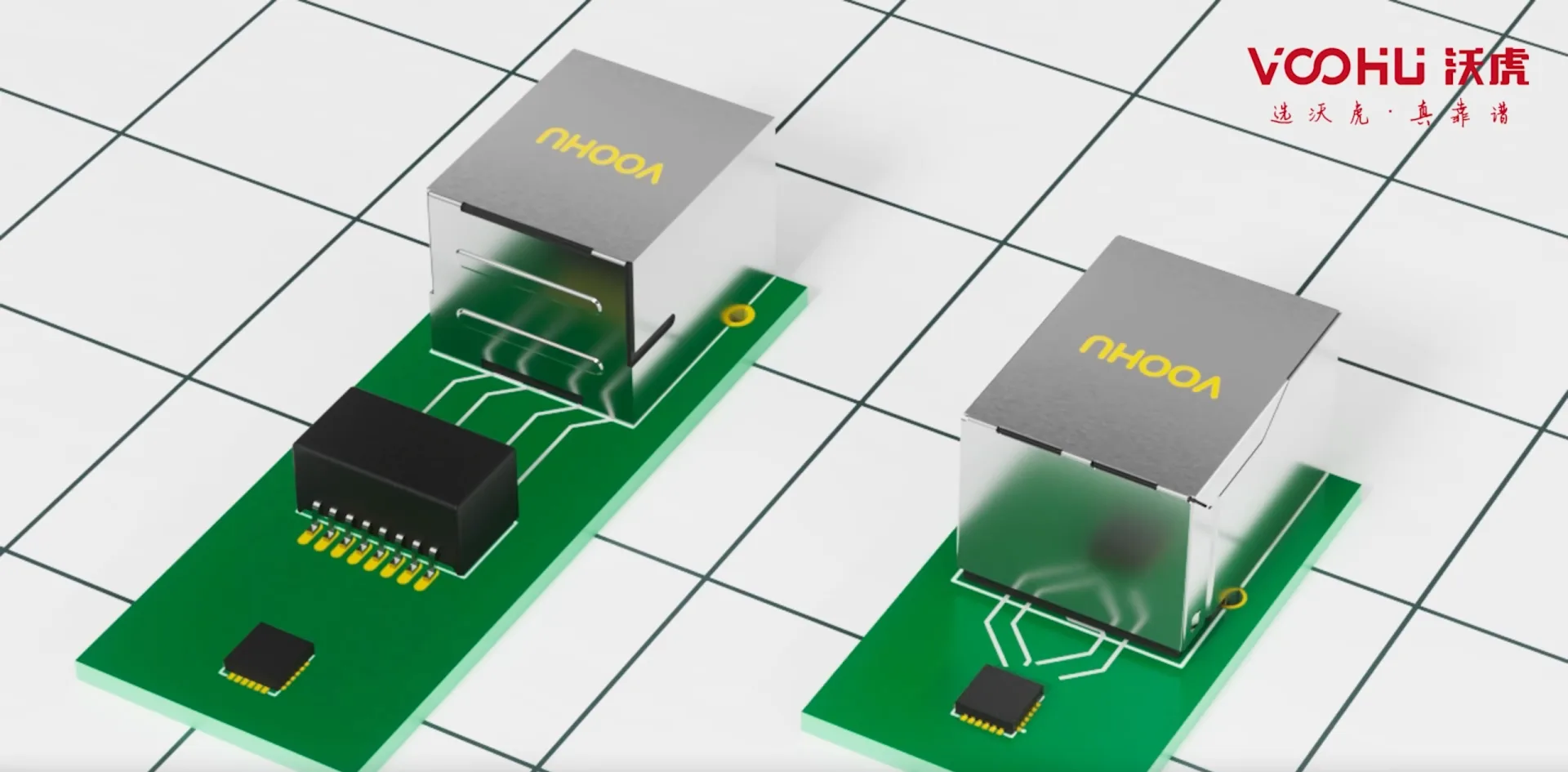
A complete PD power chain is: RJ45 → tap power from the LAN transformer center taps → rectifier bridge (polarity- and A/B-tolerant) → PD controller (hot-swap, classification, UVLO) → isolated DC-DC (flyback) → output. Data still runs through the differential windings, while PoE DC is injected/extracted at the center taps. So this Gigabit LAN transformer must carry the PoE DC bias current at its center tap without saturating — the most commonly overlooked constraint on the data side; get it wrong and insertion loss degrades and packets drop.
Why PD Isolated Supplies Are Almost Always Flyback
The PoE bus spans 37-57V, and the spec requires the PD output to be isolated from the cable/earth (safety, breaking ground loops, passing hi-pot). The flyback topology is single-switch, low-cost, inherently isolated and tolerant of wide input, making it the workhorse up to ~30W; only at Type4's 51-71W do active-clamp flyback or two-switch forward become preferable. In every case, energy storage and isolation both rest on the transformer — it is storage inductor and isolation barrier at once, so a small selection error ripples into efficiency, temperature rise, EMI and safety.
Four Critical Design Points of the Flyback Transformer
First, the turns ratio Np:Ns sets the reflected voltage and duty cycle; size it for the worst case — 57V input, lowest output — with derating margin for the main MOSFET: too high and the reflected voltage risks breaking the switch, too low and the duty cycle widens and secondary stress rises. Second, primary inductance Lp sets DCM vs CCM, peak current and ripple; too small and peak current soars and the core saturates and heats, too large and dynamic response slows and size grows. Third, leakage inductance — its spike must be absorbed by an RCD snubber, which is both loss and an EMI source; the winding technique (sandwich, primary/secondary interleaving) directly sets leakage. Fourth, the core and bobbin — the window area and creepage of EP/EFD cores decide how much power and how high an isolation voltage you can reach. VOOHU PoE power transformers span EP7/EP10/EP13/EFD15/EFD20/EFD25, laid out along the PoE class power gradient.
Solution: Pick the Core by PoE Class and Pass Certification First Time
Estimate Power by PoE Class First, Then Size the Core
PD available power is set by PoE class: 802.3af (Type1) ~12.95W, 802.3at (Type2/PoE+) ~25.5W, 802.3bt Type3 ~51W, Type4 ~71W. After cable loss and efficiency, multiply the net output power by 1.2-1.5 as margin when picking the core; never choose the smallest core at the power limit — PoE cameras run at full load year-round and core temperature rise adds on top of ambient. Rule of thumb: ≤13W use EP7/EP10, ~25W use EP13/EFD15, ~50W use EFD20, ~70W use EFD25 or switch to a two-switch topology. For secondary-side filtering, add a low-DCR molded power inductor (WHYT series) to cut ripple and temperature rise; for hot-swap and bus surge, clamp the PoE bus transient with a bidirectional TVS, working with the LAN transformer for staged protection.
PoE PD Power-Chain Quick Selection Table
| PoE Class / PD Available Power | Isolated-Supply Design Notes | VOOHU Selection Advice |
|---|---|---|
| 802.3af Type1 / ≤12.95W (out ~10W) | Flyback DCM; size turns ratio for 57V input, 30% MOSFET margin | PoE power transformer EP7 / EP10 core (compact, low cost) |
| 802.3at PoE+ Type2 / ≤25.5W (out ~21W) | Lp at the CCM boundary; control peak current and core temp rise | PoE power transformer EP13 / EFD15 core |
| 802.3bt Type3 / ≤51W (out ~43W) | Larger window and heatsinking; watch creepage for hi-pot | PoE power transformer EFD20 core |
| 802.3bt Type4 / ≤71W (out ~60W) | Near the flyback limit; prefer active-clamp or two-switch forward | PoE power transformer EFD25 core (or custom) |
| PoE injection on the data path (all classes) | Center tap must carry PoE DC bias without saturating | Gigabit LAN transformer WHSG / WHDG series (PoE bias margin) |
| Output filtering / secondary rail | Low DCR, low temp rise, small size | Molded power inductor WHYT series |
Don't Overlook: Layout, Thermal and Three Pre-Certification Checks
Once the flyback is chosen, the last mile is often lost to layout and thermal design: keep the primary high-di/dt loop (MOSFET-transformer-input cap) as short and small as possible, place the RCD snubber close by to shrink the radiating area, and spread apart the heat of the transformer, PD controller and rectifier bridge, adding copper pour or a thermal pad under the core where needed. Before certification, run three self-checks: full-load core temperature rise (leave ~15C margin over ambient), hi-pot at 1500VAC/1min without breakdown, and a radiated scan across 30-230MHz for harmonics from the leakage spike. Pass all three and formal certification usually passes first time, saving rounds of rework and prototype cost.
Conclusion: Get the Core Right and the PD Supply Is Both Easy and Reliable
A PD isolated supply looks like "just copy the reference design," but what actually separates reliable products is whether the flyback transformer keeps enough power and thermal margin for its PoE class, whether the turns ratio is designed for the 57V worst case, and whether leakage and creepage make room for EMI and hi-pot. Treat the VOOHU PoE power transformer range (full EP/EFD line) as a standard shelf — pick the core by class first, then fine-tune turns ratio and inductance — pair it with a Gigabit LAN transformer that tolerates PoE bias, a low-DCR molded inductor and a bus TVS, and a PoE camera, AP or gateway will pass certification first time and run cool at full load. That is the reliability VOOHU aims to give engineers, and it matters most in always-on security & monitoring applications.
Frequently Asked Questions (FAQ)
Q1. What does the PoE cable connect to first, and why is isolation mandatory?
Power is tapped at the LAN transformer center taps, rectified into the PD controller, then fed to the flyback isolated DC-DC. Isolation is mandated by 802.3: it keeps the cable side safely isolated from the device output (passing 1500VAC+ hi-pot) and breaks ground loops while suppressing common-mode noise. The flyback transformer is that isolation barrier.
Q2. How do I estimate the flyback turns ratio?
Design for the worst case: input at the 57V bus maximum, output at target voltage plus diode drop; reflected voltage = (Np/Ns)x(Vout+VD). Set the maximum duty cycle near 0.45 and leave ~30% breakdown margin on the main MOSFET, then back out the ratio. Too high risks breaking the switch; too low raises secondary current stress and cuts efficiency.
Q3. What do I do about an overheating transformer?
First separate core loss from copper loss. A too-small Lp drives excessive peak current, or a core chosen too small runs near saturation — both heat up. Step the EP core up to an EFD, increase Lp, and check the air gap and turns. For always-on PoE cameras, size the core at 1.2-1.5x the output power rather than at the limit.
Q4. For 802.3at 25.5W, EP13 or EFD15?
It depends on thermal and size constraints. Tight space with modest ambient favors EP13; sustained full load or high ambient favors the larger-window EFD15, which runs cooler and clears safety creepage more easily. VOOHU stocks both; leave a pin-compatible footprint so you can step between the two cores later.
Q5. How do I fix high output ripple or high no-load loss?
Ripple is mainly a secondary-filtering issue: enlarge the output capacitor and add a low-DCR molded inductor (WHYT series) as a second-stage filter for a clear improvement. High no-load loss usually comes from high switching frequency and large leakage spikes; use a PD controller with light-load frequency/Burst modes and optimize the RCD snubber to cut standby loss.
Q6. How much PoE current can the LAN transformer center tap carry — will it saturate?
A single Gigabit PoE port carries ~0.6A DC (more for Type3/Type4), so choose a LAN transformer whose center tap is rated with PoE bias margin (e.g. WHSG/WHDG series), where the anti-bias current is spec'd at or above that value. A generic transformer with no PoE rating will bias the core, worsening insertion loss and even dropping packets.
Q7. How do I debug a failing isolation / hi-pot test?
Usually creepage and insulation are insufficient. Choose an EFD core with a large window and adequate bobbin creepage, add margin tape and triple-insulated wire between primary and secondary, and ensure 1500-3000VAC/1min without breakdown. VOOHU PoE power transformers ship hi-pot tested; just specify the required isolation level when selecting.
Q8. Can I still use a flyback at Type4 71W?
It is near the flyback limit — doable but tight on efficiency and temperature. Prefer active-clamp flyback or two-switch forward, with an EFD25 or custom core. If you insist on single-switch flyback, enlarge the core, optimize the winding to cut leakage, and run a full-load high-temperature burn-in to confirm long-term temperature rise and efficiency.