Standoff voltage
The highest voltage the device tolerates without conducting. Set it above the normal working voltage including ripple, or the part leaks in service.

Protective Component products
Bidirectional ESD parts clamp symmetrically, which differential pairs need because the signal swings either side of the common mode point. Channel to channel capacitance matching matters as much as the absolute value on a fast link.
Part number search & selector
The table uses the current English-site product records, published selection fields and part-specific technical-file links.
* Frozen Image and Part Number columns · drag horizontally to review all specifications
| Image | Datasheet | Compare | Downloads |
Polarity
|
Vrwm/V
|
Vesd Air/Vesd Contact
|
Cj/pf
|
Package
|
Operating Temperature
|
Sample |
|---|
| Image | Part number | Datasheet | Compare | Downloads | Polarity | Vrwm/V | Vesd Air/Vesd Contact | Cj/pf | Package | Operating Temperature | Sample |
|---|---|---|---|---|---|---|---|---|---|---|---|
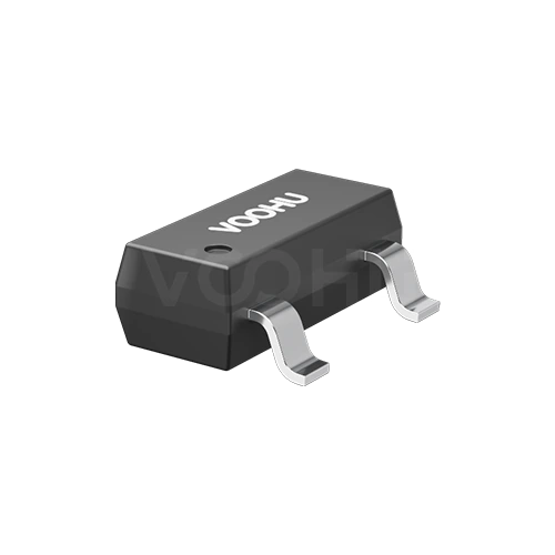 |
WHALD30E2B | SPEC | Bi-Directional ESD | 30 | ±30KV/±30KV | 0.9 | SOT-23 | -40 °C to 125 °C |
|
Broaden the selected filters or clear the current search.
By polarity
Polarity follows the signal: unidirectional for DC rails, bidirectional for AC and differential lines.
How to select
Threat first, then polarity, then the voltage window, then capacitance.
Surge energy from lightning or switching needs a TVS. Fast human-body or contact discharge on a data port needs a low capacitance ESD device.
Unidirectional suits single-polarity DC rails. Bidirectional suits AC lines and differential pairs that swing both sides of ground.
Standoff voltage above the highest normal working voltage, clamping voltage below what the protected device survives. Both have to hold.
On high speed lines, capacitance decides whether the protection is usable. Measure the eye diagram and return loss after fitting.
Parameters
Standoff and clamping voltage form a window that both has to fit inside.
The highest voltage the device tolerates without conducting. Set it above the normal working voltage including ripple, or the part leaks in service.
Where conduction begins, measured at a small stated test current. It sits above the standoff figure and below the clamping voltage.
The voltage across the device while it diverts a stated peak current. This is what the protected circuit actually sees, so compare at the same current.
Energy handling at a stated waveform, commonly 8 by 20 or 10 by 1000 microseconds. The waveform must match or the figures do not compare.
The load the device places on the line. Low capacitance parts exist specifically so high speed signals are not degraded by the protection.
Unidirectional conducts hard in one direction only. Bidirectional behaves symmetrically, which is required where the signal swings both ways.
Compare
Energy handling, response speed and capacitance separate the choices.
Return to the selector ↑| Polarity | Parts | Vrwm/V | Vesd Air/Vesd Contact | Cj/pf | Package | Operating Temperature | Action |
|---|---|---|---|---|---|---|---|
| Bi-Directional TVS | 1 | 58 | - | - | DO-214AB | -60 °C to 150 °C | Filter → |
| ESD | 3 | 3.3, 5 | ±15KV/±12KV, ±20KV/±20KV, ±30KV/±30KV | 0.3, 0.8, 1.2 | SOD323, SOT-363, DFN2510-10L | -40 °C to 125 °C | Filter → |
| Bi-Directional ESD | 1 | 30 | ±30KV/±30KV | 0.9 | SOT-23 | -40 °C to 125 °C | Filter → |
Application review
Confirm the port type, the standard to be met and the signal speed on that line.
Documents
Datasheets carry the clamping curve, pulse waveform conditions and capacitance.
Showing representative available file sets. Search to find a specific SKU.
VOOHU’s published product content is reviewed by its engineering team. Specifications, downloads and technical support information are tied to specific part numbers, so you can verify them before requesting samples or a quotation.
Category overview
Two decisions cover most of this category: which technology matches the threat, and whether the part needs to be unidirectional or bidirectional.
Discuss a new design
Contact FAE for a replacement assessment.
Already have a part number? Request samples or a quote.
A TVS diode is sized for surge energy from lightning coupling or heavy switching, rated in peak pulse power at a defined waveform. An ESD device is sized for fast, low energy static discharge and built for very low capacitance, so it can sit on a high speed line. Sizing one against the other threat gives the wrong part.
A unidirectional device conducts hard one way and blocks the other, which suits a DC rail that never goes negative. A bidirectional device is symmetric, which AC lines, differential pairs and buses swinging both sides of ground require. Fit a unidirectional part there and it conducts on the negative half.
The device sits in parallel with the signal, so its capacitance is a load the line has to drive. On a high speed pair, a few picofarads visibly degrades the eye and raises return loss. That is why low capacitance ESD parts are a separate category, and why the eye should be measured with the part fitted.
FAQ
Answers cover TVS against ESD, polarity choice, capacitance and placement.
Because each line of the pair swings both above and below the common mode level. A unidirectional device would conduct on the negative excursion and distort the signal. A bidirectional device stays high impedance across the full swing and only conducts when a discharge takes the line outside the normal range.
It adds some capacitive load. On a fast pair that shows as insertion loss and a smaller eye. What matters as much as the absolute capacitance is how well matched the two channels are, because a mismatch converts common mode noise into differential noise that lands directly on the signal.
An array saves board area, simplifies routing and usually gives better channel matching because the channels are on one die. Single devices allow each one to sit right at its own connector pin. Choose on the number of lines, the space available and how critical matching is.
Both clamp symmetrically, but an ESD part is built for low capacitance and fast response against static discharge, while a TVS is sized for surge energy. On a high speed pair the ESD part is usually the right choice; where both threats exist, the two are sometimes combined in stages.
With a complete part number, send the part number, quantity, delivery region and the date you need it. If you are still selecting, send the interface type, the data rate, the number of lines and the discharge level you must withstand.
Engineer support
Send the candidate part number and the condition you need reviewed. Sample support can be added after the selection is clear; commercial questions may be discussed in the same engineering conversation.
Include the document revision
Temperature, isolation voltage and PoE current basis
Pin count, pitch and spacing between pin rows
To help prioritize samples and evaluation
When you need candidates and a comparison of differences
Engineering review identifies candidate parts and explains the differences.
From the selector or engineering review
Prototyping / pilot build / production
Specify sample and production timing separately
Compliance documents, material declarations or third-party reports
Samples are free of charge. Sample quantity and lead time depend on the part number and project stage. Sales will respond on business days.