Different PHY wiring principles
The following is a detailed analysis of the differences and design considerations between voltage-based PHY and current-based PHY in network transformer applications, combined with actual scenarios and technical requirements:
────────────────────────────────────────────────
1. Differences between voltage-based PHY and current-based PHY
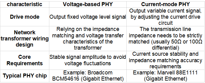
Summary of key differences
- Driving principle
- Voltage-type PHY: directly outputs a specific voltage signal (such as a 2.5V swing).
- Current-type PHY: driven by a current source, the output current is determined by the line impedance and the required voltage.
- Network transformer selection
- Voltage type: Focus on the transformer primary/secondary voltage ratio (e.g. 1:1 or 1:2).
- Current type: The impedance of the transformer needs to be matched (such as 1:1CT, center tap is used for common mode rejection).
- Impedance matching design
- Voltage type: A terminating resistor (such as a 100Ω differential resistor) may be required on the secondary side of the transformer.
- Current type: A matching resistor network (such as a 25Ω resistor in series + a 100Ω resistor in parallel) needs to be set on the PHY side.
────────────────────────────────────────────────
2. Differences in network transformer wiring design
1. Typical wiring of voltage-based PHY
-
Wiring diagram:
PHY TX ± → Transformer primary ± → Secondary ± → RJ45 (center tap connected to filter capacitor + VDD)
Design points:
-
The center tap needs to be connected to the PHY power supply (e.g. 2.5V) through a capacitor (e.g. 0.1μF).
-
The secondary side needs to terminate the differential line with a 100Ω resistor to suppress signal reflection.
2. Typical wiring of current-mode PHY
- Wiring diagram:
PHY TX ± → matching resistor → transformer primary ± → secondary ± → RJ45 (center tap connected to common mode inductor)- Design points:
- The PHY side requires impedance matching through a series resistor (e.g. 25Ω) and a parallel resistor (e.g. 100Ω).
- The center tap should be connected to a common mode inductor or directly to ground (depending on the PHY manual requirements).
────────────────────────────────────────────────
3. Design considerations
1. Notes on voltage-based PHY
- Power supply stability: The center tap power supply needs to be low-noise. It is recommended to use LDO power supply and add decoupling capacitors (such as 10μF+0.1μF).
- Termination resistance accuracy: 100Ω differential resistors must have 1% accuracy to avoid clock jitter caused by signal reflection.
- Signal amplitude debugging: The oscilloscope detects whether the signal swing meets the standard (such as 1V peak-to-peak value) to prevent insufficient PHY driving capability.
2. Notes on current-mode PHY
-
Impedance matching network: Design matching resistors strictly according to the PHY manual (example: 25Ω series + 100Ω parallel).
-
Current source protection: To avoid output short circuit, PHY may be damaged due to overcurrent.
-
Common-mode noise suppression: The center tap increases the common-mode inductance (e.g. 10mH) to improve EMI performance.
3. Common points of attention
- Transformer selection: It must support the operating frequency (10/100/1000BASE-T corresponds to different frequency bands).
- PCB wiring rules:
- Differential lines are strictly equal in length (±5 mil), evenly spaced, and impedance error is controlled to be ≤10%.
- The distance between PHY and transformer is ≤50mm to reduce path loss.
- EMC design:
- Place an isolated ground plane near the network transformer.
- Add TVS diodes to prevent surge damage.
────────────────────────────────────────────────
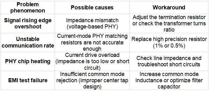
4. Common Errors and Solutions
────────────────────────────────────────────────
V. Conclusion
-
Voltage-type PHY: suitable for low-cost, medium- and low-speed scenarios (such as 10/100M). The circuit design is simple but requires strict voltage regulation.
-
Current-type PHY: used in high-speed/high-precision scenarios (such as Gigabit Ethernet), requiring precise impedance matching and noise suppression.
-
Core principles:
-
Design the network transformer peripheral circuit according to the PHY chip manual.
-
Focus on Signal Integrity (SI) and Electromagnetic Compatibility (EMC).
Select the appropriate PHY type based on actual needs and use simulation tools (such as ADS/HFSS) to optimize performance during design.
![[New Product Recommendation] CAT6A 10 Gigabit Waterproof RJ45 Coupler Male and Female](/upload/image/20260717/4694ba2c3b52b9d273512e3777f53f84.jpg)