




【Frequently Asked Questions about Components】Solutions to Common Component Problems at Voohu Electronics - Part 1
【Frequently Asked Questions about Components】Solutions to Common Component Problems at Voohu Electronics - Part 1
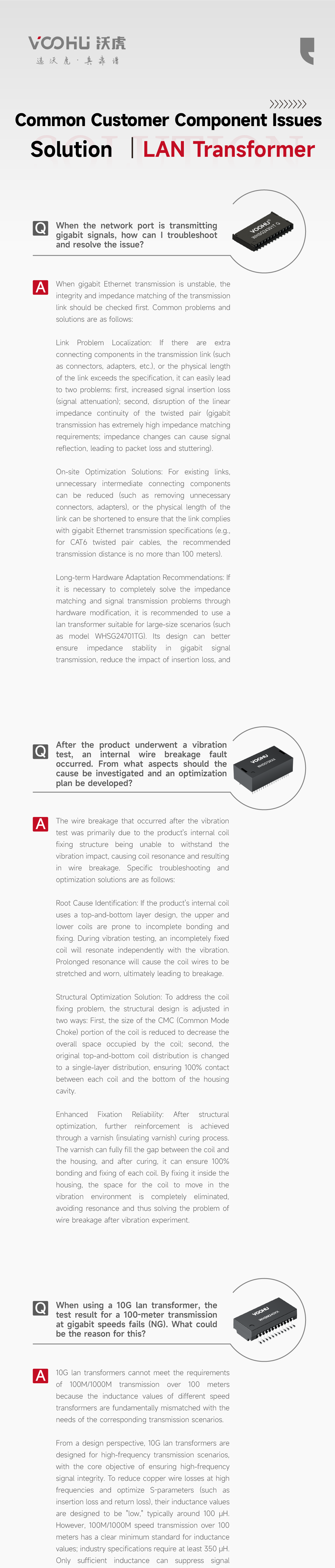

Text Version (Q&A)
The following is the text version of the images above, for easier search and reference.
LAN Transformer
Q1: When the network port is transmitting gigabit signals, how can I troubleshoot and resolve the issue?
A: When gigabit Ethernet transmission is unstable, the integrity and impedance matching of the transmission link should be checked first. Common problems and solutions are as follows:
Link Problem Localization: If there are extra connecting components in the transmission link (such as connectors, adapters, etc.), or the physical length of the link exceeds the specification, it can easily lead to two problems: first, increased signal insertion loss (signal attenuation); second, disruption of the linear impedance continuity of the twisted pair (gigabit transmission has extremely high impedance matching requirements; impedance changes can cause signal reflection, leading to packet loss and stuttering).
On-site Optimization Solutions: For existing links, unnecessary intermediate connecting components can be reduced (such as removing unnecessary connectors and adapters), or the physical length of the link can be shortened to ensure that the link complies with gigabit Ethernet transmission specifications (e.g., for CAT6 twisted pair cables, the recommended transmission distance is no more than 100 meters).
Long-term Hardware Adaptation Recommendations: If it is necessary to completely solve the impedance matching and signal transmission problems through hardware modification, it is recommended to use a lan transformer suitable for large-size scenarios (such as model WHSG24701TG). Its design can better ensure impedance stability in gigabit signal transmission, reduce the impact of insertion loss, and improve transmission reliability.
Q2: After the product underwent a vibration test, an internal wire breakage fault occurred. From what aspects should the cause be investigated and an optimization plan be developed?
A: The wire breakage that occurred after the vibration test was primarily due to the product's internal coil fixing structure being unable to withstand the vibration impact, causing coil resonance and resulting in wire breakage. Specific troubleshooting and optimization solutions are as follows:
Root Cause Identification: If the product's internal coil uses a top-and-bottom layer design, the upper and lower coils are prone to incomplete bonding and fixing. During vibration testing, an incompletely fixed coil will resonate independently with the vibration. Prolonged resonance will cause the coil wires to be stretched and worn, ultimately leading to breakage.
Structural Optimization Solution: To address the coil fixing problem, the structural design is adjusted in two ways: first, the size of the CMC (Common Mode Choke) portion of the coil is reduced to decrease the overall space occupied by the coil; second, the original top-and-bottom coil distribution is changed to a single-layer distribution, ensuring 100% contact between each coil and the bottom of the housing cavity.
Enhanced Fixation Reliability: After structural optimization, further reinforcement is achieved through a varnish (insulating varnish) curing process. The varnish can fully fill the gap between the coil and the housing, and after curing, it can ensure 100% bonding and fixing of each coil. By fixing it inside the housing, the space for the coil to move in the vibration environment is completely eliminated, avoiding resonance and thus solving the problem of wire breakage after the vibration experiment.
Q3: When using a 10G lan transformer, the test result for a 100-meter transmission at gigabit speeds fails (NG). What could be the reason for this?
A: 10G lan transformers cannot meet the requirements of 100M/1000M transmission over 100 meters because the inductance values of different speed transformers are fundamentally mismatched with the needs of the corresponding transmission scenarios.
From a design perspective, 10G lan transformers are designed for high-frequency transmission scenarios, with the core objective of ensuring high-frequency signal integrity. To reduce copper wire losses at high frequencies and optimize S-parameters (such as insertion loss and return loss), their inductance values are designed to be "low," typically around 100 μH. However, 100M/1000M speed transmission over 100 meters has a clear minimum standard for inductance values; industry specifications require at least 350 μH. Only sufficient inductance can suppress signal attenuation in long-distance transmission and ensure interference immunity for stable transmission.
Because the inductance of 10G lan transformers (around 100 μH) is far below the 350 μH minimum required for 100M/1000M transmission over 100 meters, the signal suffers excessive attenuation and reduced interference immunity, ultimately causing the test to fail (NG).
RJ45 Connector
Q4: Is it necessary to install an additional TVS diode between the PHY chip and the integrated RJ45 connector?
A: Whether or not a TVS diode should be installed between the PHY and the integrated RJ45 depends primarily on the product's requirements for EFT (Electrical Fast Transient/Burst) and surge protection testing:
If the product has explicit EFT/surge protection standards (such as IEC 61000-4-4, IEC 61000-4-5, etc.), it is recommended to install a TVS array protection device between the differential signal pairs. These devices effectively absorb excess energy generated by EFT transient pulses and surge impacts, preventing interference from entering the PHY chip through the signal link and ensuring stable chip operation.
If the product does not have relevant EFT/surge testing requirements, and the integrated RJ45 already has a basic protection design, then it can be determined at the discretion of the user based on the actual application scenario (such as whether it is in a complex electromagnetic environment), and there is no mandatory requirement to install a TVS array.
Q5: If the LED indicator light on the RJ45 connector has inconsistent brightness, how can I troubleshoot and resolve the issue?
A: Inconsistent LED brightness in RJ45 connectors requires prioritizing the identification of the root cause based on the specific design, followed by targeted solutions. Specifically:
If the customer's current circuit design is difficult to adjust (e.g., current-limiting resistors, driver circuits, etc. cannot be modified), the brightness inconsistency is most likely related to differences in the parameters of the LED devices themselves (e.g., individual variations in forward voltage and luminous efficiency among different LEDs).
In such cases, it is recommended to replace the LEDs with customized LED components with higher parameter consistency — the customization process strictly controls key parameters such as forward voltage and luminous flux, ensuring uniform LED performance within the same batch and application scenario, thereby resolving the brightness inconsistency issue.
Q6: How can an RJ45 chip be used to change the color of an LED light?
A: The color-changing function of LEDs on an RJ45 connector is primarily achieved through the electronic switching function of the PHY chip (physical layer chip). The specific logic is as follows:
The PHY chip, as the core of network signal processing, typically integrates control circuitry and an electronic switch module for the LED indicators. When it is necessary to switch LED colors (e.g., switching red/green/yellow based on network speed or connection status), the PHY chip can output different control signals to drive the internal electronic switch and change the LED's current path.
For example, it can switch the power supply circuit for different colored LEDs, or adjust the current direction of a dual-color LED, thereby achieving automatic or on-demand color switching without the need for additional complex external mechanical switches or control circuits.
Protective Component
Q7: What are the core protection functions of a TVS diode (transient voltage suppressor diode)? How is it used in a circuit to provide protection?
A: The core protection function of a TVS diode is to suppress transient high-voltage pulses in a circuit, preventing damage to sensitive devices due to transient interference. Its specific functions and typical application scenarios are as follows:
In terms of protection, a TVS diode can respond to transient high voltages within an extremely short time (typically nanoseconds). When a transient pulse exceeding the normal operating voltage (such as electrostatic discharge or electrical fast transient burst, EFT) appears in the circuit, the TVS diode quickly switches from a high-resistance state to a low-resistance state, diverting the excess energy of the transient pulse to ground and clamping the circuit voltage within a safe range. This achieves a dual protection effect: electrostatic discharge (ESD) protection and transient pulse suppression (such as EFT).
From an application perspective, if a TVS diode is deployed on the "primary side" of a circuit (such as near external interfaces, power inputs, or other front-end components prone to interference), it can directly intercept transient interference (such as electrostatic discharge or EFT pulses) entering from the outside, preventing interference from propagating to sensitive back-end devices (such as chips and core modules) in advance. This maximizes its protective function and reduces damage or malfunction of downstream devices caused by transient impacts.
Q8: What role does GDT play in Ethernet communication?
A: A gas discharge tube (GDT) is an overvoltage protection device based on the principle of gas discharge. Under normal operating conditions, it has high impedance and barely affects circuit operation. When a transient voltage reaches its breakdown voltage, the gas inside the tube is ionized, forming a low-resistance path, allowing the overcurrent to be quickly discharged to ground. GDT's protective role in Ethernet communication:
High-Energy Transient Overvoltage Protection: GDTs have extremely high surge withstand capability, capable of withstanding surge currents of up to 10kA or more. In Ethernet communication, GDTs are often used as the first level of protection, effectively discharging high-energy transient overvoltages such as lightning-induced surges and protecting downstream circuits from damage.
Ultra-Low Capacitance Characteristics: GDTs have extremely low inter-electrode capacitance, typically less than 1pF. This characteristic means that they do not significantly affect signal integrity during high-frequency signal transmission, making them ideal for protecting Ethernet communication ports.
Application in Multi-Level Protection Schemes: In Ethernet communication equipment, GDTs are often used in conjunction with other protection components such as TVS arrays to construct multi-level protection schemes. The GDT is responsible for discharging the large current, while the TVS array quickly clamps the residual voltage, together improving the device's anti-interference capability.
Q9: If a network port fails the Electrical Fast Transient/Burst (EFT) test (NG), what targeted optimization measures should be taken?
A: The core issue behind an NG result in network port EFT testing is that transient pulse interference has not been effectively suppressed. Protection devices need to be installed precisely at the key nodes of the network port signal link (the PHY side and the RJ side of the lan transformer), while paying attention to device selection and compatibility. Specific solutions are as follows:
PHY-side transient voltage suppression: Install a TVS (Transient Voltage Suppressor) diode between the differential signal pairs of the lan transformer near the PHY chip. TVS devices have a fast response speed and can conduct quickly when a transient pulse appears, clamping the excessive transient voltage on the differential lines within a safe range, preventing interference from entering the PHY chip and causing malfunctions, thus blocking the impact of pulse interference on the core chip.
RJ-side high-voltage/lightning protection: Connect a GDT gas discharge tube in series between the center tap of the lan transformer near the RJ45 connector and ground. Under normal operation the GDT remains highly insulating and does not affect network signal transmission; when subjected to high-voltage impacts (such as lightning-induced voltage or strong EFT pulses), it quickly breaks down and diverts the high-voltage interference to ground, protecting the link from high-voltage damage.
Furthermore, device selection must match testing requirements: TVS diodes need to account for the network port signal operating voltage, transient response speed, and parasitic capacitance (to avoid affecting high-speed transmission), while GDTs require attention to breakdown voltage and current-carrying capacity, ensuring compliance with the level requirements of EFT testing standards such as IEC 61000-4-4.
![【Application Solution]】Ethernet PoE: PD-side Circuit Design and Lightning Protection Solution](/upload/image/20251027/551721cdd5a9ff37e463d72d991cb3f2.jpg)




