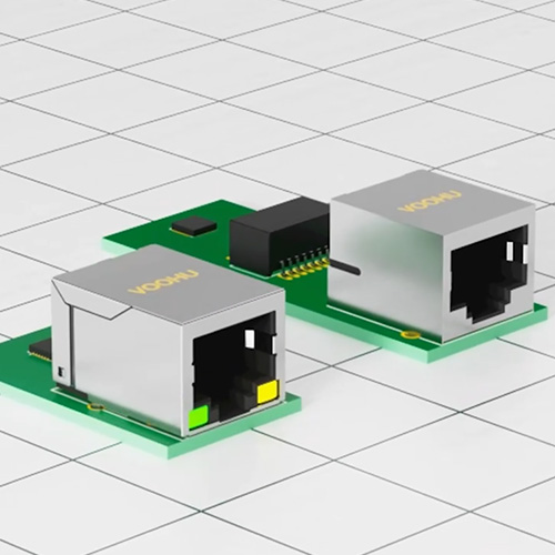
VOOHU SPE single-pair Ethernet connector selection: plug-in board socket, press-fit plug and PoDL wiring harness verification
VOOHU SPE single-pair Ethernet connector selection: plug-in board socket, press-fit plug and PoDL wiring harness verification
The SPE single-pair Ethernet prototype communicated normally when short jumpers were used in the laboratory. However, after replacing it with a formal wiring harness, link training slowed down, bit errors increased, or the load temperature rise was high. Such problems often do not occur at a single point in the PHY. Board-end sockets, cable-end plugs, crimp terminals, twisted pairs, strain relief and shielding circuits together form a connection chain. As long as one of the links changes the contact resistance, differential symmetry or return path, the original conclusion established on the bare board may become invalid.
The official website of VOOHU in Chinese and English is currently available for verification.WHSPE00467withWHSPE00468Two SPE connectors. The former is 2 PIN, Socket, 4A, 60V, plug-in type; the latter is 2 PIN, Plug, 4A, 60V, crimping type. The two public records establish clear sample branches for the board end and wiring harness end, but the page does not fully list the supporting terminals, applicable wire diameters, plating, contact resistance, plug-in life, temperature, shielding structure, IP grade or data rate. This article only uses checkable fields, does not write missing specifications into product promises, and lists drawings, terminal and cable matching, crimping process and entire channel verification as necessary steps before finalizing materials.
1. First separate the board end, wiring harness end and PoDL boundary to avoid answering the entire link with one parameter.
4A and 60V are the connector's public rating fields, which do not mean the system can directly output 240W.
Multiplying the rated current by the rated voltage results in a value that does not represent the available power of the SPE or PoDL system. The actual power supply capability is also subject to the cross-sectional area and length of the cable conductor, terminal contact resistance, crimping quality, connector temperature rise, ambient temperature, contact status after plugging and unplugging, PSE and PD circuits, surge and protection strategies, and the PoDL category adopted by the project. The design input should separately record the connector rated field, single contact continuous current, wire harness voltage drop, allowable temperature rise and system power budget, and then use the current complete data and prototype to test the closed loop. The 4A and 60V of the official website are suitable as the primary screening entrance and cannot alone form the power supply commitment of the whole machine.
Having the same 2 PIN does not automatically mean that any plug and socket can be matched with each other.
The same number of cores only means that the number of signal contacts is the same, but it does not prove that the mating interface, polarization, foolproofing, locking, terminal position, insertion depth and tolerance are exactly the same. Used for formal selectionWHSPE00467withWHSPE00468Confirm whether the current mechanical diagram belongs to the specified pairing relationship, and check the pin position direction of the front view and the board end view. If the wiring harness factory only purchases terminals and shells based on "2-core SPE", it is easy to fail to lock, insufficient contact depth, or A/B wires are reversed during the trial assembly stage. The complete suffixes of sockets, plugs, terminals, cables and accessories should be frozen in the BOM at the same time, instead of just writing the series name.
The wire diameter, insulation outer diameter and stripping length of the crimp terminal must be confirmed together.
Press-fit plugs do not just clamp any twisted pair. The conductor crimping area is responsible for forming stable metal contact, and the insulation crimping area is responsible for stress relief. Both rely on the matching of terminals and wires. A wire diameter that is too small may result in insufficient crimping height and pull-out; a wire diameter that is too large may damage the terminal or cut off part of the conductor; stripping the wire too long will leave exposed conductors and change the local impedance; stripping the wire too short may press the insulation layer into the conductor area. The applicable wire diameter and crimping height are not listed on the public product page, so these data must be obtained from controlled drawings or supplier materials before mass production, and converted into a process card that can be executed by the wire harness factory.
2. SPE has only one pair of signal lines and still needs to control differential symmetry, shielding and mechanical stress.
The twisted pair structure should be kept as far as possible in the contact area to reduce untwisting and asymmetric branches.
The point where the harness end is stripped from the outside to between the two conductors entering the terminal is usually the point in the channel where symmetry is most likely to be lost. Excessive untwisting, inconsistent lengths between the two conductors, different terminal crimping directions, or extra bends on one side will change the local impedance and increase mode conversion. The process design should write the allowable untwisting length, conductor direction, terminal orientation and finished product bending radius into the drawings, and measure them with actual wire rods and final plugs. The board end should also allow the two signal lines to enter the socket solder pins with similar geometry to avoid bypassing, changing layers or connecting additional test branches on one side first.
The shielding, reference ground and chassis overlap need to be closed loop according to the whole machine plan.
Some SPE applications require shielded cables and metal casings, while some projects use unshielded structures. Whether to shield, where to terminate the shield, and how to handle the chassis ground and digital ground should be determined by the system EMC architecture and cannot be inferred based on the appearance of the connector. The current public parameters of the two products do not list the shielding fields, so the article does not assume their specific shielding structures. During the review, the actual drawings and objects should be checked, and the connector shell, cable shielding, board edge copper, chassis overlap and protective device reflow should be placed in the same path diagram.
The plug-in board socket is not only an electrical interface, but also a stress point on the edge of the board.
WHSPE00467The public wiring method is plug-in type, and the English page corresponds to THT. In addition to signal routing, PCB design also needs to check aperture, tolerance, board thickness, device height, opening direction, forbidden area and panel position according to the current mechanical drawing. The plugging and unplugging force should not be borne entirely by the solder joints or narrow copper foil; if the structure is subject to frequent plugging and unplugging, lateral pulling or vibration, the load should be shared by the panel, shell or special fixed structure. The public page does not give the insertion and extraction force and mechanical life, and you cannot set numerical conclusions by yourself. They should be determined by the current specifications and project mechanical specifications.
3. Use two real on-shelf material numbers to create sample branches for the board end and wiring harness end.
The information in the table below comes from the VOOHU Chinese and English SPE catalog and product details page accessible on August 12, 2026. "On Shelf" means that public product records are currently verifiable and does not represent real-time inventory, pricing or delivery dates. The table only lists the number of cores, shapes, rated fields and wiring methods that are consistently disclosed on the official website; the pairing relationship, terminals, wires and mechanical dimensions still need to be confirmed through current controlled data.
| Application and verification branch | Verifiable VOOHU material number | Official website public fields and next steps |
|---|---|---|
| Board-end sockets: Check hole locations, openings, panels, soldering, and differential routing | WHSPE00467 | SPE connector; 2 PIN; Socket; 4A; 60V; plug-in type (English page THT). Obtain current mechanical drawings to confirm mating relationships with plugs, pin locations, hole locations, tolerances, and undisclosed electrical/mechanical parameters. |
| Wire harness end plug: Check terminals, wire diameter, crimp, lock and untwist length | WHSPE00468 | SPE connector; 2 PIN; Plug; 4A; 60V; Crimp type (English page Crimp). Obtain matching terminal and wire range, crimp specifications, mechanical drawings and undisclosed electrical/mechanical parameters. |
These two items are suitable for forming two verification objects in the same project:WHSPE00467Place it on the board end, focusing on reviewing hole locations, openings, panel relationships, welding and differential routing;WHSPE00468Place it at the wire harness end, focusing on checking the matching of terminals and wires, crimping cross-section, pulling force, locking and untwisting length. Both pages give 4A and 60V, but do not give the contact resistance, temperature rise curve, wire diameter range and matching tolerance required by this article, so mass production release cannot be completed based on the web page alone.
4. From drawings to wiring harness process, use four steps to lock the complete connection system
Step 1: Freeze the connection stack instead of just a socket part number
Build a connection stack inventory: board-side receptacles, harness-side plugs, mating terminals, cable types and lengths, conductor sizes, jackets and shields, strain reliefs, seals or jackets, panel openings, and assembly tools. Each item records the complete suffix and data version, and indicates whether it is the responsibility of the PCB factory, wiring harness factory or complete machine factory. If the project requires PoDL, also record the PSE/PD role, continuous and starting current, allowable voltage drop, thermal environment and fault protection. Only when the entire set of inputs is fixed can subsequent crimping and channeling results be reproduced.
Step 2: Use the mechanical drawing and the actual object to confirm the fit, polarity and board edge position.
The mechanical review must at least check the mating surface of the plug and socket, the direction of the A/B contacts, the latch and foolproofing, the insertion and extraction space, the direction of the cable outlet, the PCB hole position, the height of the device and the panel tolerance. 3D models can be used for early interference inspection, but they cannot replace physical fit and dimensional inspection. After the sample is in place, the final plate thickness and panel should be used for the first assembly. Observe whether additional lateral force is needed, whether the lock is fully in place, whether the wire harness is bent against the shell, and the confirmed views should be written into the assembly instructions.
Step 3: Turn crimp appearance, cross-section and tension into a controlled process
The first piece of wiring harness cannot be judged only by its appearance. The stripping and crimping heights and tools should be set according to the current terminal and wire materials, and the conductor crimping, insulation support, bell mouth, brush tail, terminal deformation and locking after insertion into the housing should be checked. Conduct cross-sectional analysis and tensile testing on representative samples, and record the crimping mold, equipment, operator, wire batch and terminal batch. The specific height and pulling force limits must come from current controlled information or confirmed by both parties. This article does not write its own values for unpublished specifications.
Step 4: Put supply voltage drop, temperature rise and communication performance into the same verification matrix
The PoDL prototype should simultaneously record the current, voltage drop at both ends of the plug and socket, connector and cable temperature, link status and error count under specified wire length, environment and equipment status. The test covers both stable load and specified states such as startup, load step, disconnection and reconnection, and hot plugging. If the voltage drop or temperature rise is abnormal, the board end solder joints, socket contacts, plug contacts, crimp points, and conductors should be inspected in sections rather than directly attributing the problem to the connector rating. Electrical and communications data use the same timeline, making it easier to identify whether power supply transients trigger link anomalies.
5. Use a set of reproducible prototypes and mass production to test the quality of closed-loop wire harnesses
Establish a short baseline first, then gradually increase wire length, joints and mechanical stress
Under the same PHY, firmware, PCB and test mode, first establish the link and error baseline with the confirmed short harness, then switch to the target length and least favorable routing path. Record negotiation or training time, bit errors, reconnection times and long-term running status; add TDR, return loss or other channel measurements specified by the project when conditions permit. Then before-and-after comparisons of wire harness bends, slight connector disturbances, temperature changes, and vibrations were added to distinguish purely electrical margin deficiencies from contact or mechanical issues.
Repeat electrical and communication checks after plug, pull and bend tests
Mechanical testing cannot just record "no falling off". After completing the project-specified mating, holding, pulling, or bending cycles, lockout, terminal setback, crimp points, contact voltage drop, temperature rise, and communications stability should be rechecked. For intermittent problems, the harness posture can be slightly changed under continuous flow and load and error counts can be observed simultaneously, but destructive actions beyond specifications must not be used in lieu of formal testing. The failed samples should be kept in their original state and analyzed in layers according to board ends, mating surfaces, terminals, crimps and wires.
Mass production acceptance requires binding terminals, wires, tools and inspection records
When using the same plug housing with different terminals or wires, the crimp window and channel behavior may change. Mass production documents should lock the BOM, terminal reels, wires, crimping molds, equipment parameters, first article cross-section, tension sampling, continuity and polarity testing, and specify change trigger conditions. The board end controls aperture, solder fill, device tilt and panel assembly. Any significant changes to terminals, wire, tooling, board thickness, or supply batches should be returned to the original verification matrix for impact assessment.
6. Frequently Asked Questions (FAQ)
The connector is marked 4A, 60V, does it mean that the PoDL system can provide 240W?
Not equal to. 4A and 60V are only rated fields on the current connector page; system power is also limited by PoDL scheme, cable voltage drop, contact temperature rise, environment, PSE/PD and protection strategy. The complete power supply chain must be verified according to project specifications and cannot be directly multiplied.
As long as they are both 2 PIN, can the SPE plug and socket be directly matched with each other?
You can't judge like this. Also check mating interface, polarization, latch, contact location, tolerances and complete suffix.WHSPE00467withWHSPE00468The current mechanical drawings and supplier matching confirmation should be used as the basis, and the first article assembly should be completed with physical objects.
If the crimped wiring harness passes the tensile test, does it mean that high-speed communication must be stable?
cannot. Pull force only verifies mechanical retention; communication is also affected by untwisting length, two-wire symmetry, terminal deformation, local impedance, and the entire channel. It should be judged based on the crimping cross section, polarity conduction, channel test specified in the project, bit error and load operation.
Can the SPE connector itself determine 10BASE-T1, 100BASE-T1 or 1000BASE-T1?
You can’t just rely on the connector page to decide. The rate is determined by the PHY, magnetic and common-mode components, connectors, cables, PCB and channel length; the rate field is not disclosed on the current details page. The project should freeze the target physical layer and channel specifications, and verify the final channel after obtaining complete high-frequency data.
Conclusion
WHSPE00467withWHSPE00468It can be used as the sample entrance for the board end and wire harness end; before mass production, pairing, crimping, temperature rise and channel verification must still be completed according to the specific suffix.