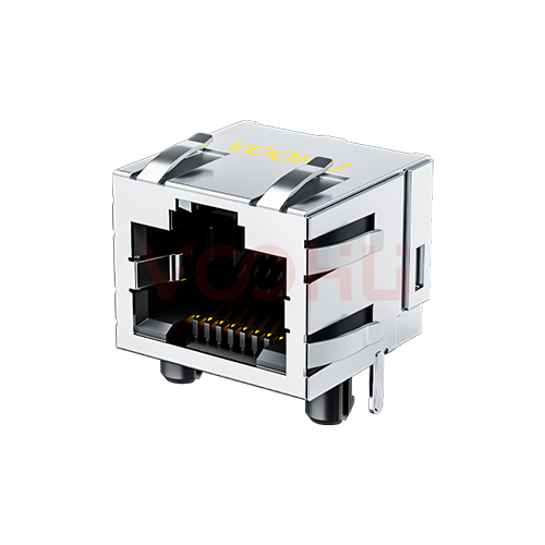
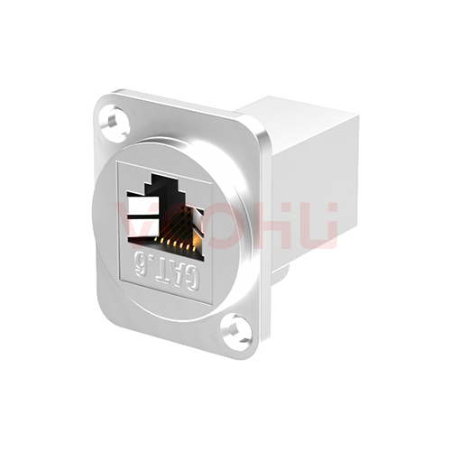
SYT561188HWA1DB4 90° side insertion 1X1 Tab Up RJ45 straight through 56 without light with shield
SYT561188HWA1DB4 90° side insertion 1X1 Tab Up RJ45 straight through 56 without light with shield
Request a Quote
Leave your details and we will send a tailored volume quote.
Our sales team will contact you within 1 business day.
Contact Sales
Reach our sales team for pricing and lead time.

Submitted
We have received your request. Our sales team will contact you within 1 business day.


For technical assistance, please click the button below to add customer service or visit the sample request page to fill out the form. We will serve you as soon as possible.
Technical Support Email: fae.thorne@voohu.cn Phone: +86 400-1048-018
For more details, please visit the Download Center to get documents or click the button below to add customer service. We will serve you as soon as possible.


For small-volume orders, you can place orders directly on VOOHU Shop. We support VAT general/special invoices with a convenient and efficient process.
For technical assistance or sample requests, please click the button below to add customer service or visit the sample request page to fill out the form. We will serve you as soon as possible.
Customer Service Email: song.lei@voohu.cn Phone: +86 180 2130 1120
VOOHU Electronics holds ISO 9001:2015 international quality management system certification, ISO 14001:2015 environmental certification, RoHS environmental certification, REACH certification, and CE certification.
On the VOOHU official website, you can quickly select products online through product categories or parameter filters (such as data rate, package type, operating temperature, current, etc.). You can also visit the "Solution" page to view recommended solutions that match your needs. For further support, you can directly contact the technical support team and provide your application scenario — we will accurately recommend the optimal solution for you.
Gold-plating thickness directly affects contact resistance and service life. Commercial-grade RJ45 plating is typically 3-6 μin, suitable for general office environments; industrial grade is recommended to be ≥15 μin, effectively resisting oxidation and fretting corrosion. Plating that is too thin causes contact resistance to rise and the signal bit-error rate to increase after long-term use. VOOHU's standard RJ45 series has a contact gold-plating thickness of ≥15 μin and a mating life of ≥750 cycles.
It can be judged simply from three aspects: First, visually inspect that the housing has no cracks or burrs, the gold pins are evenly plated with no oxidation/discoloration, and the shielding shell is ≥0.2 mm thick. Second, use a multimeter to check that contact resistance between contacts is on the order of tens of mΩ and insulation resistance is ≥1000 MΩ. Third, there should be a clear "click" locking sound during mating, and no looseness when wiggled after insertion. In industrial environments, an additional withstand-voltage test is recommended: no breakdown at 1000 VAC/60s between adjacent terminals.
It mainly depends on the electromagnetic interference intensity of the application environment. Unshielded RJ45 is suitable for office networks and ordinary indoor equipment—low cost and flexible to wire. Shielded RJ45 is suitable for strong EMI/RFI environments such as industrial workshops, medical equipment, and outdoor cabinets; it requires shielded cabling and proper grounding to be effective. Note that shielding must be consistent across the entire link—the connector, cable, and equipment end must all be grounded, otherwise the shield layer instead becomes an antenna.