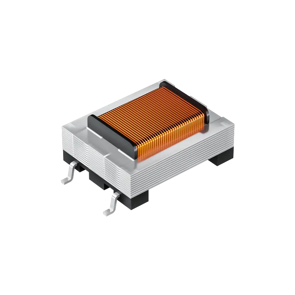
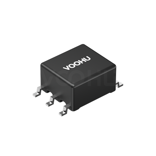
WHTT4205 4PIN SMD Hi-Pot1250VAC Audio Transformer
Request a Quote
Leave your details and we will send a tailored volume quote.
Our sales team will contact you within 1 business day.
Contact Sales
Reach our sales team for pricing and lead time.

Submitted
We have received your request. Our sales team will contact you within 1 business day.


For technical assistance, please click the button below to add customer service or visit the sample request page to fill out the form. We will serve you as soon as possible.
Technical Support Email: fae.thorne@voohu.cn Phone: +86 400-1048-018
For more details, please visit the Download Center to get documents or click the button below to add customer service. We will serve you as soon as possible.


For small-volume orders, you can place orders directly on VOOHU Shop. We support VAT general/special invoices with a convenient and efficient process.
For technical assistance or sample requests, please click the button below to add customer service or visit the sample request page to fill out the form. We will serve you as soon as possible.
Customer Service Email: song.lei@voohu.cn Phone: +86 180 2130 1120
VOOHU Electronics holds ISO 9001:2015 international quality management system certification, ISO 14001:2015 environmental certification, RoHS environmental certification, REACH certification, and CE certification.
On the VOOHU official website, you can quickly select products online through product categories or parameter filters (such as data rate, package type, operating temperature, current, etc.). You can also visit the "Solutions" page to view recommended solutions that match your needs. For further support, you can directly contact the technical support team and provide your application scenario — we will accurately recommend the optimal solution for you.
An audio transformer mainly provides:
(1) Impedance matching—matching a high-impedance source (such as a tube amplifier output of a few kΩ) to a low-impedance load (such as a 4-16Ω speaker) for maximum power transfer.
(2) Signal isolation—eliminating ground-loop noise between stages and suppressing AC hum and common-mode interference.
(3) Balanced/unbalanced conversion—converting a single-ended signal to a balanced signal (or vice versa) to improve common-mode interference immunity, commonly seen in professional audio equipment.
(4) Voltage transformation—achieving passive signal amplification or attenuation.
(1) Avoid ground loops—the grounds on the two sides of the transformer should be kept separate, isolated only internally through the transformer, and must not be directly connected on the PCB.
(2) Ground the shield layer—if the transformer has an electrostatic shield (Faraday shield), it should be grounded at a single end (usually the source-side ground) to reduce capacitively coupled noise.
(3) Keep away from strong magnetic interference sources—such as power transformers and inductors; maintain a sufficient safe distance based on the interference source's power and magnetic-shielding level, preferably placing the audio transformer in an area away from strong magnetic components, or use a magnetic shielding can.
(4) Input/output wiring should use twisted-pair or shielded cable, with the shield grounded at a single point on the source side.
(5) For microphone-level signals, prefer audio transformers with permalloy (Mu-metal) shielding to resist low-frequency magnetic-field interference.
The impedance Z of an audio transformer is not DC resistance, but the AC impedance determined by inductance at a specific frequency (usually 1kHz). Its core formula is Z = 2πfL, meaning the lower the frequency, the lower the impedance. DC resistance represents only the purely resistive loss of the coil wire, whereas impedance Z determines the efficiency of signal transmission, the frequency-response characteristics, and the accuracy of impedance matching.