
【Frequently Asked Questions】Placement of Common‑Mode Choke in Ethernet Transformers: Detailed Explanation for Non‑PoE and PoE Scenarios – VOOHU
【Frequently Asked Questions】Placement of Common‑Mode Choke in Ethernet Transformers: Detailed Explanation for Non‑PoE and PoE Scenarios – VOOHU
In Ethernet hardware circuit design, the LAN Transformer is a core component that ensures signal transmission and provides electrical isolation. The isolation transformer and common‑mode choke (CMC), as the two key supporting components of the Ethernet transformer, directly determine the signal integrity and EMC immunity of the equipment.
VOOHU Electronics (Suzhou) has been deeply involved in the R&D and solution adaptation of Ethernet supporting components such as LAN Transformers and common‑mode chokes for many years. Based on a large number of engineering implementation cases, it has been found that most R&D engineers face the same design challenge: should the common‑mode choke be placed on the side of the LAN Transformer closer to the PHY chip, or on the side closer to the RJ45 Connector (cable side)?
According to VOOHU’s technical team measured data and industry standard design guidelines, there is no universal answer to CMC placement. The core depends on two major factors: the PHY driver type (current‑mode or voltage‑mode), and whether the device supports Power over Ethernet (PoE). Below, VOOHU explains the design logic, working principle, and selection/layout guidelines for each scenario, helping engineers avoid hidden pitfalls in circuit design.
Core Working Principle of the Common‑Mode Choke (CMC)
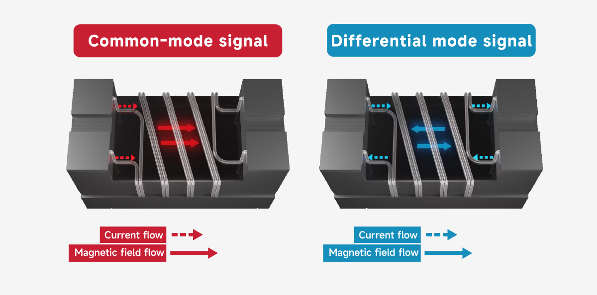
To accurately grasp the CMC layout logic, one must first understand its filtering principle. Internally, a CMC consists of two coils wound in the same direction with the same number of turns, housed in the same magnetic core. It is specifically designed to suppress common‑mode noise during differential signal transmission in Ethernet, and is a core filtering component in VOOHU’s Ethernet transformer supporting solutions.
Under normal operation, for the differential working signal transmitted by the equipment, the magnetic fluxes generated by the two coils are equal in magnitude and opposite in direction, thus cancelling each other. The signal passes through the choke without loss or distortion. For common‑mode interference noise caused by external ESD or radiation, the noise flows through the coils and creates magnetic fluxes that add in the same direction, making the CMC exhibit high impedance, blocking the noise at its source and preventing it from affecting communication stability.
Based on the basic principle of the CMC and considering PoE power feeding, VOOHU classifies two types of layout solutions, suitable for most consumer and industrial Ethernet equipment.
Non‑PoE Scenarios: CMC Position Determined by PHY Driver Type
In non‑PoE scenarios where only data communication is required (no 48V power delivery), the industry typically uses a discrete LAN Transformer module that integrates the isolation transformer and CMC, together with an external RJ45 jack to complete the network connection. In this scenario, there is no high‑voltage DC bias, so core saturation is not a concern. The only determining factor is the PHY driver architecture. VOOHU provides differentiated layout recommendations based on this:
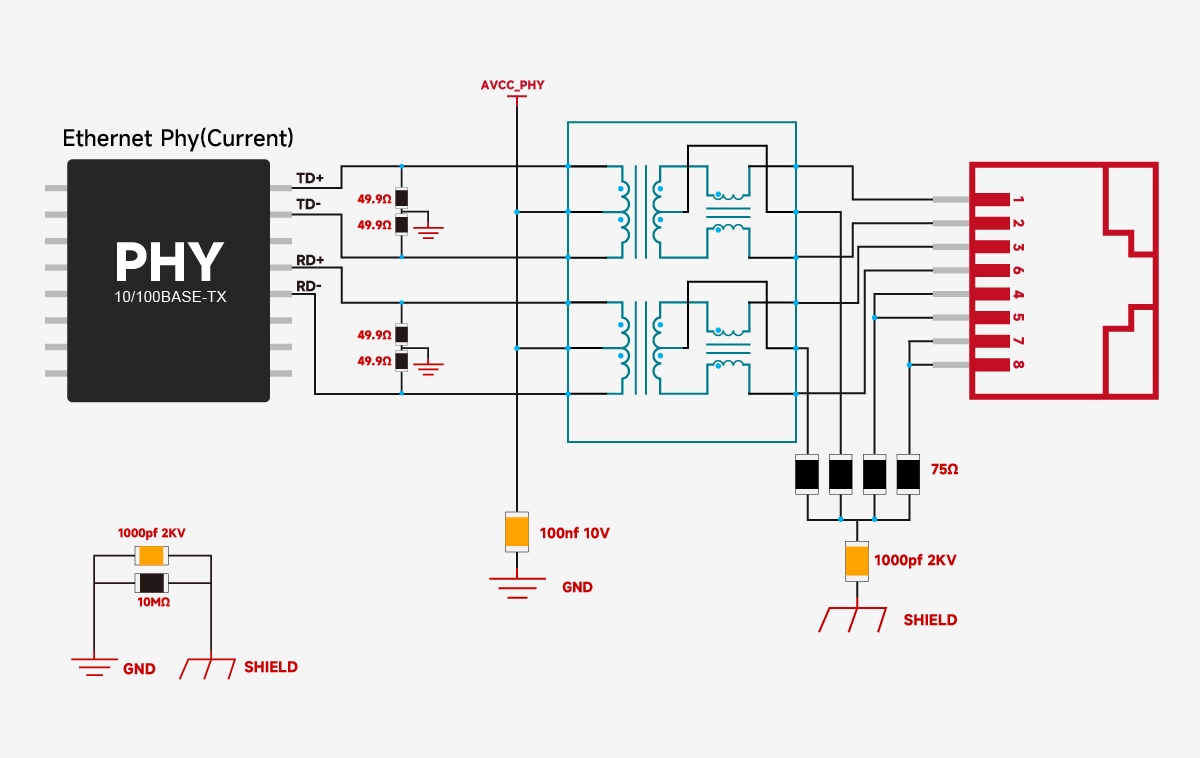
Current‑Mode PHY: Mandatory placement on the cable side (RJ45 side)
The transmitter of a current‑mode PHY is equivalent to a constant current source. Its working principle relies on an external load to convert the constant current signal into a voltage signal. Its center tap must be connected to a 2.5V/3.3V supply voltage to establish a complete DC bias path for the constant current source.
This type of PHY is extremely sensitive to series inductance in the signal return path, which is a common mistake in circuit design.
If a conventional 2‑wire CMC is placed between the PHY and the transformer, the series inductance of the CMC will impede dynamic current changes in the return path, destroying the low‑impedance return path and directly causing signal waveform distortion and differential amplitude imbalance. In severe cases, the network link may be disconnected and the device unable to connect.
Therefore, for a current‑mode PHY, the 2‑wire common‑mode choke must be placed on the secondary side of the transformer, close to the RJ45 cable side, to avoid signal anomalies from the hardware level.
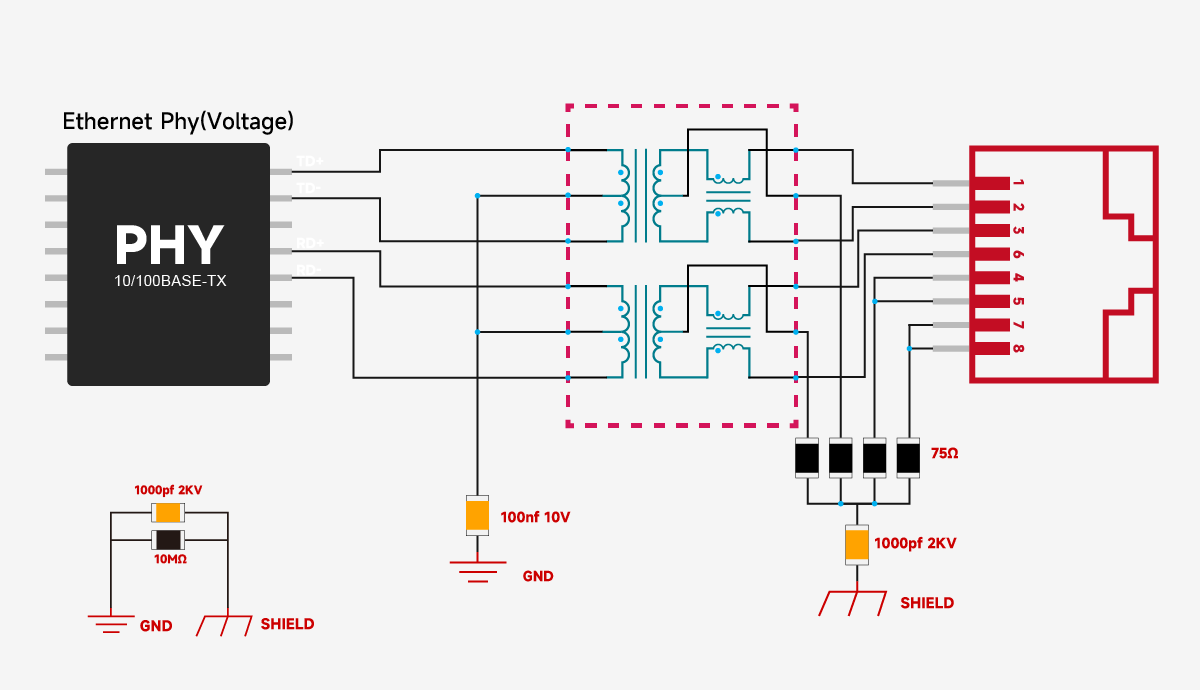
Voltage‑Mode PHY: Flexible placement, can be adapted as needed
The architecture of a voltage‑mode PHY is significantly different. Its transmitter is equivalent to a voltage source. Its center tap does not need a direct connection to power; only a capacitor to ground is required for biasing. It has much higher tolerance to series inductance in the signal return path.
Whether the CMC is placed on the PHY side or the RJ45 cable side, it will not impair signal integrity or affect communication performance.
To simplify PCB layout and reduce procurement and assembly costs, in conventional non‑PoE voltage‑mode PHY solutions, VOOHU integrates the CMC directly inside the LAN Transformer by default, providing customers with a one‑stop solution for filtering and isolation.

PoE Scenarios: Avoiding Core Saturation is the Core Design Principle
PoE scenarios are commonly used in industrial switches, surveillance cameras, wireless APs, etc. They rely on 48V DC high voltage to simultaneously transmit data and power. In this scenario, the DC bias introduces a risk of core saturation in the CMC, which is a major challenge in PoE Ethernet transformer design.
VOOHU’s technical team emphasises: in PoE scenarios, the PHY driver type does not matter. All chip architectures must be designed around preventing CMC core saturation.
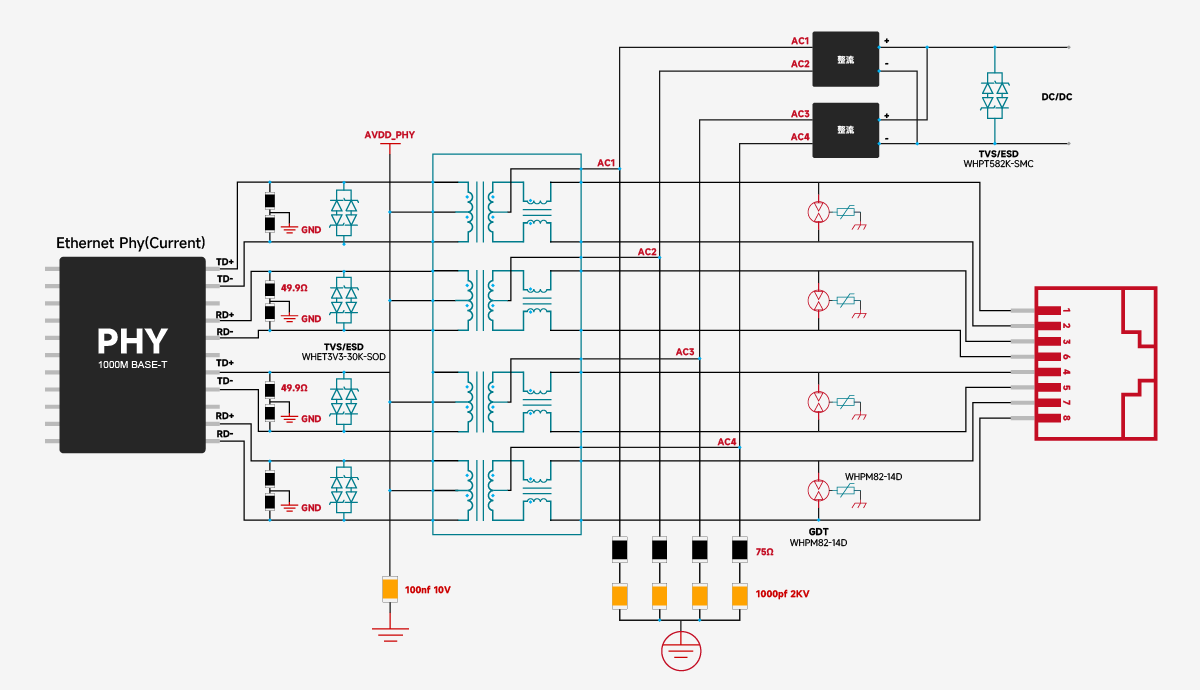
Optimal solution: Place the CMC on the PHY side
TVS diodes should be placed as close as possible to the bus connector or transceiver pins, with short and wide traces. It is recommended to connect one TVS between the A and B lines (differential‑mode protection) and additionally one TVS from each line to ground (common‑mode protection).
Constrained layout: Conditions and drawbacks of cable‑side placement
If PCB size or mechanical layout constraints force the CMC to be placed on the RJ45 cable side, a conventional 2‑wire common‑mode choke must never be used. Instead, a customised 3‑wire dedicated CMC with a center tap (such as those from VOOHU) must be used, allowing the 48V DC current to go through the center tap directly into the transformer, bypassing the CMC windings, thereby avoiding core saturation and preventing EMI filtering failure.
Special note: 3‑wire CMCs have more complex manufacturing processes, higher material costs than ordinary 2‑wire products, and more difficult routing. They are only suitable for special constrained scenarios and are not recommended as a general solution for PoE devices. For mass‑produced PoE products, VOOHU strongly recommends the use of PoE MagJacks with integrated internal structures (CMC and transformer integrated into one component) to reduce R&D and production risks.
Selection and Layout Recommendations
Non‑PoE scenarios
Current‑mode PHY: 2‑wire CMC fixed on the RJ45 cable side; Voltage‑mode PHY: No mandatory CMC placement. Prefer integrated LAN Transformers with built‑in CMC to simplify PCB design.
PoE scenarios:
Current‑mode PHY: 2‑wire CMC fixed on the RJ45 cable side; Voltage‑mode PHY: No mandatory CMC placement. Prefer integrated LAN Transformers with built‑in CMC to simplify PCB design.
General caution:
In PoE scenarios, never place an ordinary 2‑wire CMC directly on the RJ45 side. Doing so easily causes core saturation, excessive EMI radiation, packet loss, and other faults, increasing later debugging costs.
For different PHY chip specifications and PoE power levels, VOOHU (Suzhou) can provide customised LAN Transformer and common‑mode choke selection and layout support, helping enterprises shorten development cycles and improve communication stability and electromagnetic compatibility.
FAQ
Q1: In non-PoE designs, should the common-mode choke (CMC) be placed on the PHY side of the LAN transformer or on the RJ45 cable side?
A: It depends on the PHY driver type. The transmitter of a current-mode PHY is equivalent to a constant current source and is extremely sensitive to series inductance in the signal return path — if a conventional 2-wire CMC is placed between the PHY and the transformer, its series inductance destroys the low-impedance return path, causing waveform distortion and differential amplitude imbalance, and in severe cases link disconnection. So for a current-mode PHY, the 2-wire CMC must be placed on the secondary side of the transformer, close to the RJ45 cable side. A voltage-mode PHY has much higher tolerance to series inductance: either placement works without impairing communication performance, and in conventional non-PoE voltage-mode solutions VOOHU integrates the CMC directly inside the LAN transformer by default to simplify PCB layout and reduce cost.
Q2: In PoE designs, where should the CMC be placed?
A: In PoE scenarios the PHY driver type does not matter — all architectures must be designed around preventing CMC core saturation, because the 48V DC bias is the source of the saturation risk. If PCB size or mechanical constraints force the CMC onto the RJ45 cable side, a conventional 2-wire CMC must never be used: a customized 3-wire CMC with a center tap (such as those from VOOHU) is required, so the 48V DC current goes through the center tap directly into the transformer and bypasses the CMC windings, avoiding core saturation and EMI filtering failure. 3-wire CMCs are more complex to manufacture, more expensive, and harder to route, so they only suit constrained scenarios; for mass-produced PoE products VOOHU recommends PoE MagJacks with the CMC and transformer integrated into one component, reducing R&D and production risks.
Q3: What happens if an ordinary 2-wire CMC is placed directly on the RJ45 side in a PoE design?
A: The 48V DC bias can easily saturate the CMC core, which leads to EMI filtering failure, excessive radiation, packet loss and other faults, and significantly increases later debugging costs. This is the general caution for PoE LAN transformer design: never place an ordinary 2-wire CMC directly on the RJ45 side — use PHY-side placement, a 3-wire center-tapped CMC, or an integrated PoE MagJack instead.
![[FAQ] Three FAQs for integrated RJ45 (Mag-Jack) application](/upload/image/20260724/fd7e9c7a96b2d92065dbdd6aff0b38b3.jpg)