【Standard Circuit Design】Isolated SPI Solution Standard Circuit Reference
This solution is VOOHU Electronics (VOOHU)'s standard isolated SPI solution. The company has focused on the field of communication electronic components for over 9 years, adhering to the business philosophy and service concept of "Choose VOOHU – Truly Reliable", and providing comprehensive technical solution support.
Technical Background and Core Concepts
Isolated SPI Communication
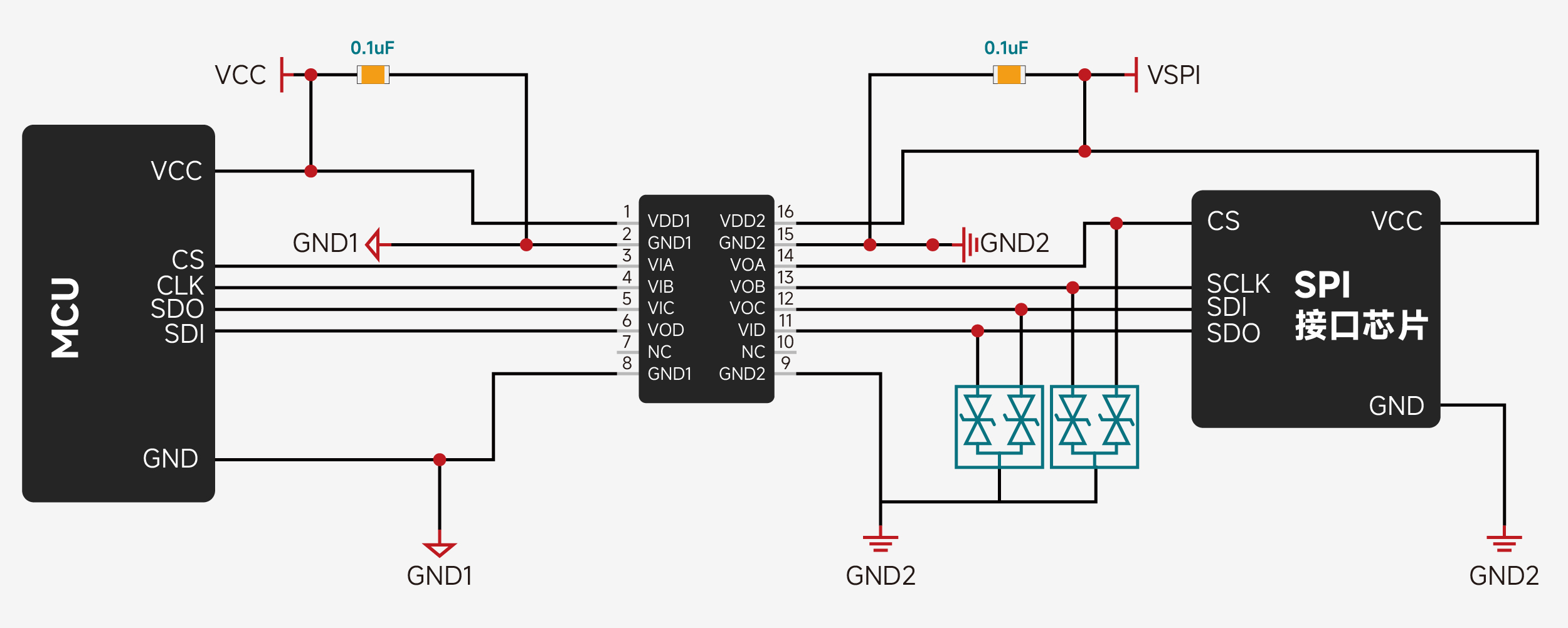
SPI (Serial Peripheral Interface) adopts a master‑slave synchronous, full‑duplex architecture, completing communication via four lines: Chip Select (CS), Serial Clock (SCLK), MOSI, and MISO. It features simple timing and high speed, making it the mainstream interface for ADCs/DACs, sensors, AFEs, and other devices. However, standard SPI assumes that the transmitter and receiver share a common ground and operate in close proximity on the same board. Once communication crosses boards, power domains, or involves significant potential differences between the two ends, ground loops and common‑mode interference directly threaten communication integrity. Isolated SPI retains the high‑speed synchronous transmission characteristics of SPI while establishing an electrical isolation barrier between the two ends through digital isolators, transformers, or capacitive coupling. This gives the transmitter and receiver independent power supplies and grounds, capable of withstanding voltage differences of hundreds or even thousands of volts, fundamentally breaking ground loops, suppressing common‑mode noise, and safely extending SPI into industrial, automotive, energy storage, and other high‑voltage, high‑interference environments.
Why is this technology needed?
In scenarios such as BMS battery management, energy storage systems, servo drives, industrial control, and automotive electronics, there are often significant potential differences and strong electromagnetic interference between high‑voltage and low‑voltage sides, or between boards. This imposes stringent requirements on electrical isolation, common‑mode rejection, sampling accuracy, and personnel and device safety.
The SPI protocol itself possesses inherent advantages of high speed, full‑duplex operation, and deterministic timing, but it does not define isolation or protection mechanisms. Without appropriate physical‑layer circuitry, ground potential differences, common‑mode noise, surge shocks, and ESD will erode signal integrity – causing bit errors in mild cases or chip breakdown in severe cases – making it difficult to realise SPI's speed advantages in harsh environments.
A proven isolated SPI standard circuit design reference helps developers choose the appropriate isolation method (digital isolator / transformer / capacitive coupling) on the signal chain, complete impedance matching and decoupling filtering, provide comprehensive over‑voltage and ESD protection for ports, and ensure physical‑layer consistency through standardised power domain partitioning and grounding practices. This fully unlocks the potential of the SPI protocol, significantly shortens development cycles, reduces trial‑and‑error costs, and makes isolated communication systems truly stable and reliable.
VOOHU's SPI solution abandons the bulky wiring harness of traditional parallel buses, adopting an isolated SPI topology that precisely connects each SPI slave board in series with adjacent boards, forming a "digital neural chain" from the cell module to the terminal BMU.
Technical Solution Details
Isolated SPI Circuit Design
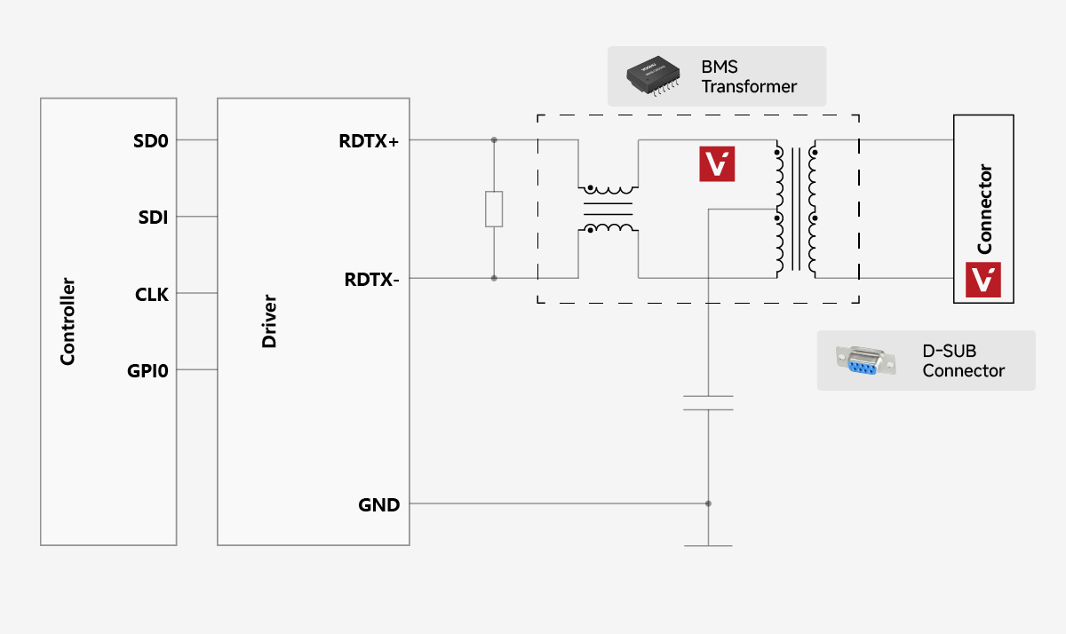
Primary Side Wiring:
-
SPI signal connection: The SPI signals (SDO, SDI, CLK, GPIO) from the controller side are connected to the primary‑side inputs of the BMS isolation transformer through a driver.
-
Decoupling capacitor: A 100nF capacitor should be placed close to the primary‑side power pin, connected to GND, to ensure driver supply stability and signal integrity.
Secondary Side Wiring:
-
Differential signal connection: The secondary‑side differential outputs (RDTX+/RDTX−) should be connected to the corresponding pins of the isolation connector, then communicated externally through a D‑SUB connector.
-
TVS protection: TVS protection devices should be placed before all RDTX+/RDTX− pins to suppress surge shocks, and bypass capacitors of appropriate value should be connected to secondary ground. 0402 or 0603 package SMD ceramic capacitors are recommended, placed as close as possible to the connector pins.
Circuit Function Description
-
Signal isolation: The BMS isolation transformer transmits SPI differential signals via magnetic coupling, achieving complete electrical isolation between the controller side and the battery side, effectively blocking the high‑voltage current path, protecting the main MCU from high‑voltage shocks, and suppressing common‑mode interference.
-
Decoupling capacitor: The 100nF capacitor filters high‑frequency noise on the driver‑side power supply, ensuring stable operation of the isolation transformer primary side and signal integrity.
-
TVS protection: The clamping voltage of the TVS devices should match the system operating voltage, providing bidirectional surge and ESD protection for the RDTX differential pins, ensuring long‑term reliable operation in high‑voltage isolation environments.
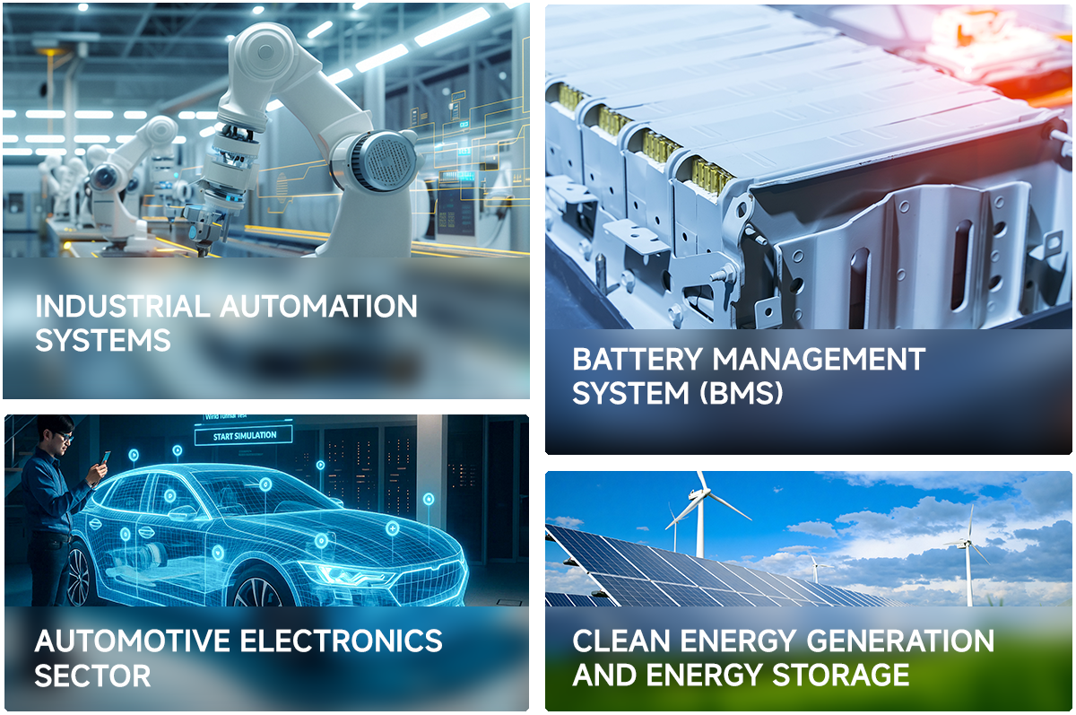
Typical Application Scenarios
-
Battery Management System (BMS)
Scenarios: EV power battery packs, energy storage power stations, cell‑sampling AFE daisy‑chains -
Renewable Energy Generation and Energy Storage
Scenarios: PV inverters, wind power converters, PCS energy storage converters -
Industrial Automation and Motor Drives
Scenarios: Servo drives, variable frequency drives, PLC analog acquisition, robot joints -
Automotive Electronics
Scenarios: Electric drive controllers, OBC on‑board chargers, DC‑DC converters, high‑voltage distribution units (PDU)
Note: The above solutions are standard designs for reference only. The final circuit design shall be based on on‑site requirements. For in‑depth support, please contact us free of charge.
From its founding in 2018 to its overseas expansion in 2026, VOOHU Electronics has become a reliable partner for more than 1,000 enterprises by virtue of “excellent quality, fair pricing, attentive service, and reliable delivery.”
If you are also looking for a telecommunications electronic component supplier that saves you worry, money, and effort, why not try VOOHU? After all, the choice of more than 100 listed companies can’t be wrong.
Choose VOOHU – Truly Reliable. That is not just a slogan; it is an answer written by the trust of 1,000+ customers over nine years.
If you need detailed product technical information, or sales and technical support, please visit the VOOHU official website at www.voohu.cn. You can select products in the “Product Centre”, contact us via “Contact Us” or the online assistant, or fill in the form under “Technical Support” in the official WeChat menu. We will arrange for a specialist to assist you as soon as possible.