VOOHU Practical Combat: Rectification of Excessive Conducted Harassment (CE) at the DC Power Port of Network Equipment—Selection Guide for Power Line Common Mode Inductors and Integrated Inductors
VOOHU Practical Combat: Rectification of Excessive Conducted Harassment (CE) at the DC Power Port of Network Equipment—Selection Guide for Power Line Common Mode Inductors and Integrated Inductors
Introduction: Why "conducted harassment" always explodes in the last week of the project
Network equipment such as switches, PoE gateways, IP cameras, and industrial gateways often only take two or three weeks to function, but it can take two months to be stuck in the EMC laboratory. One of the most common and annoying is the power terminal conducted emission (CE). EN 55032/CISPR 32 and GB/T 9254 set two limit lines for the disturbance voltage of the power port in the 150kHz~30MHz frequency band, Class A and Class B. The quasi-peak limit of Class B at 0.5~5MHz is only 56dBμV, while many prototypes are measured at 65~70dBμV, and it is common to exceed the standard by 5~15dB.
What makes engineers even more troublesome is that "rectification is ineffective": a common mode inductor is connected to the DC input port, and the spectrum line does not move; replace it with a larger impedance, the low frequency is suppressed, and it becomes warped above 10MHz; the Y capacitor is increased and the leakage current cannot be passed. The root of the problem is that many people use common mode inductors as "universal magnetic beads", neither distinguishing the two completely different paths of differential mode and common mode, nor matching the impedance - frequency characteristics and DC bias capability of the device with the spectrum of the noise source.
In this article, we dissect the causes of DC power port conduction disturbance from the physical layer and explain clearly, and then return to the selection: how to choose the impedance level of the power line common mode inductor (Power Line CMC), how to leave a current margin, how to suppress the noise from the source with the integrated inductor, and finally provide the rectification path and selection quick check list based on VOOHU's shelf material number.
1. Where does the noise come from: Differential mode and common mode are two completely different circuits.
1.1 Differential mode noise: switching current "spinning" in the input loop
Whether it is Buck, Flyback or forward topology, the input current is an intermittent trapezoidal wave. When the switch is turned on, the input capacitor and wiring provide a current jump of several amperes within tens of nanoseconds. This di/dt flows through the equivalent series inductance and wiring impedance of the input loop, generating a pair of anti-phase disturbance voltages on the VIN and GND lines - this is differential mode noise. Its spectrum is dominated by the switching frequency fsw (typically 300kHz~1MHz) and its harmonics. The energy is concentrated at 150kHz~5MHz, with large amplitude but rapid attenuation with frequency. To deal with differential mode, rely on the X capacitor and differential mode inductor (including the leakage inductance of the common mode inductor), not the Y capacitor.
1.2 Common mode noise: dv/dt “leaks” to ground through parasitic capacitance
The switching node (SW point or MOS drain) jumps dozens of volts every cycle, and the dv/dt can easily reach 5~20V/ns. There is a parasitic capacitance Cp of pF magnitude between the power device casing and the heat sink, between the primary and secondary parts of the transformer, and between the large piece of copper foil on the PCB and the reference ground plane. Calculated according to i = Cp·dv/dt, even if Cp is only 20pF, a 10V/ns jump can stimulate an instantaneous common mode current of 200mA. This current flows through the chassis and ground wire, and finally flows through the 50Ω sampling resistor of the LISN for testing, and is faithfully recorded as a disturbance voltage by the instrument. Common mode noise has high frequency and slow attenuation. The "hump" raised in the 5~30MHz section of the conduction spectrum line is almost all its masterpiece.
1.3 Qualify first before taking action: Don’t use common-mode medicine to treat differential-mode diseases
In practice, the judgment is not difficult: use differential mode/common mode separation network, or use the most primitive method - change the length of the ground wire, change a power adapter wire, temporarily short-circuit the Y capacitor, and observe the changes in the spectral lines. If the peak of 150kHz~2MHz increases significantly with the increase of load current and is not sensitive to changes in the ground wire, it is probably dominated by differential mode; if 5~30MHz has a wide envelope and is extremely sensitive to the connection between the ground wire and the chassis, it is dominated by common mode. Skipping this step and replacing the device directly is a typical source of "adding a common mode inductor is useless".
2. Technical analysis: Why does common mode inductor “do not work after adding it”
2.1 Impedance curve misalignment: bigger Z is not better
The common mode impedance Zcm of the common mode inductor does not rise monotonically with frequency. It reaches a peak value near the self-resonant frequency fSRF (determined by the common mode inductance Lcm and the inter-turn parasitic capacitance Cp, fSRF = 1/(2π√(Lcm·Cp))). After crossing the peak value, the impedance decreases with frequency and the overall resistance is capacitive. The "100MHz/0.1V impedance value" marked on the specification sheet is only a nominal point on the curve and cannot be directly regarded as "suppression capability." If your over-standard point is at 8MHz, but you choose a model with an impedance peak between 30 and 50MHz, the actual impedance at 8MHz may be lower than a model with medium impedance and a higher peak. Therefore, the first principle of selection is: let the impedance peak cover your over-standard frequency band, rather than copying the maximum Z value.
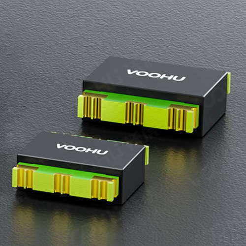
VOOHU power line common mode inductorThe impedance covers 40Ω~2500Ω (100MHz/0.1V, the reference value can be up to 3000Ω), the rated DC current is 0.9A~20A, and the rated voltage is divided into three levels: 50V/80V/125V, which corresponds to the common 12V/24V/48V/54V DC input of network equipment. If the low-frequency band (150kHz~2MHz) exceeds the standard, choose a high-inductance, high-impedance range, such as WHAL-1513A-222T0 (2200Ω) or WHAL-9070A-302T0 (3000Ω); if the mid- to high-frequency range (5~30MHz) exceeds the standard, you should choose a medium-impedance range with an impedance peak closer to the front, such as WHAL-9070A-601T0 (600Ω) or WHAL-9070A-102T0 (1000Ω).
2.2 DC bias and saturation: rated current is not “how much current can pass”
Theoretically, the ampere-turns of the two windings of a common mode inductor cancel, and DC does not produce bias magnetism. However, in reality, the winding is not completely symmetrical, and the differential mode current and leakage flux will still establish a bias magnetic field in the core; when the core cross-section is too small and the load current is close to the rated value, the magnetic permeability is suppressed, and Lcm may shrink by 30% to 50% - the beautiful sense you measured on the LCR meter "disappears" at full load, and the spectrum line naturally rebounds. Therefore, a 30%~50% margin must be left for the rated current: for an 8-port PoE switch with 54V/2.5A input, a model with a rated current ≥3.5A should be selected; for a DC 12V/1A IP camera, the 1211 or 1513 package is sufficient. For 48V/54V systems, you must choose the 125V rated voltage range, do not use the 50V range.
2.3 Leakage inductance is “free differential mode inductance”
The leakage inductance Lleak of the common mode inductor is typically 0.5%~2% of Lcm. It is a series inductor for differential mode current and naturally forms a first-level differential mode LC filter with the X capacitor. When correcting the differential mode, there is no need to rush to add an independent differential mode inductor: choose a common mode inductor with a winding structure and a slightly larger leakage inductance, and then match it with an X capacitor of 1~2.2μF. You can usually get 20~30dB attenuation at 150kHz~1MHz. But the bigger the leakage inductance is, the better - too large leakage inductance will oscillate with the input capacitor to produce a voltage spike during load transients, which needs to be matched with the input capacitor.Two-way TVSWith clamp.
2.4 Source control: integrated inductor and switching loop area
Filtering is "blocking", reducing noise sources is "thinning", and the latter is often more cost-effective. If the Buck inductor uses an open magnetic circuit wound inductor, the magnetic flux leakage will radiate directly outward and couple to the input line, and the 20dB hard-earned by the filter will be "jumped" again.Integrated (molded) inductorUsing metal magnetic powder to suppress and close the magnetic circuit, the magnetic leakage is small, the DCR is low, and the saturation characteristics are gentle, which is equivalent to weakening the noise source itself. Coupled with two things that don't cost money - making the copper foil area of the switch node "enough" (reduce Cp), and placing the input ceramic capacitor close to the VIN and GND pins of the IC (reducing the high di/dt loop area) - the overall downward shift of the conduction spectrum line by 3~8dB is a very common result.
VOOHU's WHYT / WHYTA / WHYTP series of integrated inductors cover 0.33~100μH, saturation current 1.6~24A (large size models can reach 75A), temperature rise current 1.4~16A, and sizes from 3.4×3.2×1.8mm to 17.15×17.15×7mm. 12V→5V/3.3V/1.2V multi-channel Buck on switch and gateway motherboards, commonly used models such as WHYT0650, WHYT1050, WHYT1265; multi-phase or multi-channel load point power supply scenarios, can also be usedCombined (coupled) inductorFurther reduce ripple and footprint.
2.5 Layout: the "invisible killer" of filters
No matter how good the device is, it cannot sustain three layout errors. First, the input traces of the filter are parallel to the output traces or even stacked up and down. The parasitic mutual capacitance allows high-frequency noise to directly "leap" the common mode inductor. According to actual measurements, the filtering effect can be more than 20dB. The input and output must be physically separated and isolated with ground copper. Second, the trace from the Y capacitor to the chassis ground/reference ground is too long. A few millimeters of lead inductance is enough to cause the Y capacitor to fail above 10MHz. Make sure to drill holes nearby and shorten the thick copper. Third, the common mode inductor should be as close as possible to the power inlet connector, and no switching devices that generate dv/dt should be placed at the back end, otherwise noise will be re-injected after the filter.
3. Solution: VOOHU three-step rectification method and selection checklist
3.1 Three-step rectification method
The first step is qualitative. Use a spectrum analyzer plus LISN to record the original spectral lines, and cooperate with the differential mode/common mode separation network (or change the grounding conditions) to determine whether the excess is dominated by differential mode or common mode, and record the excess frequency point and excess scalar amount (dB). This step takes half an hour and can save the next two weeks of blind auditions.
The second step is to configure the filter network. Differential mode dominance: Add the X capacitor to 1~2.2μF, use the leakage inductance of the common mode inductor to make the differential mode inductor, and add a π-type differential mode LC if necessary. Common mode dominance: Connect the power line common mode inductor in series at the DC inlet, and connect 2×2.2nF~4.7nF Y capacitor to the chassis ground to form a common mode π network; if it is still insufficient, use "two common mode inductors with different impedances in cascade" to widen the suppression bandwidth better than "one super large impedance".
The third step is to treat the source. Replace with an integrated inductor, compress the input high-frequency loop area, and add an RC buffer to the switch node (typically 100pF + 10~47Ω) to reduce dv/dt. Buffering sacrifices a few tenths of a percentage point in efficiency, a classic compromise between efficiency and EMI, but is usually much cheaper than adding another level of filtering.
3.2 VOOHU Selection Quick Check List
| Typical applications and inputs | Main over-standard frequency bands | Recommended Power Line Common Mode Inductors | Recommended one-piece inductor | Supporting components and key points |
|---|---|---|---|---|
| IP camera/access control, DC 12V ≤1A | 150kHz~2MHz, mainly differential mode | WHPL-1211A-231T0 (230Ω, small size) | WHYT0630/WHYT0640 (2.2~10μH) | X capacitor 1μF + Y capacitor 2×2.2nF; input loop area is minimized |
| Desktop switch/home router, DC 12V 1~3A | 0.5~5MHz, differential mode and common mode mixed | WHAL-1513A-101T0 (100Ω) or -222T0 (2200Ω) | WHYT0650/WHYT1030 | Use leakage inductance for differential mode; Y capacitor is close to the ground plane |
| PoE switch/PSE, 54V 2~5A | 5~30MHz, mainly common mode | WHAL-9070A-102T0(1000Ω)/ -601T0(600Ω) | WHYT1050/WHYT1260 | Must select 125V rated voltage range; cooperate with network port common mode inductor |
| Industrial gateway/PLC, DC 24V 2~4A | 150kHz~10MHz wide frequency | WHAL4520A Series / WHAL7060A Series | WHYT1250/WHYT1265 | Bidirectional TVS is connected in parallel at the input to suppress surges; two-stage filtering if necessary |
| Multi-port PoE++ / high power PSE, 54V ≥8A | 0.15~30MHz full frequency band | WHACM12A65R Series / WHACM15A60R Series | WHYT1770/WHYT2313 | High current and low DCR; focus on calculating temperature rise and heat dissipation |
| On-board POL power supply, 12V→1.2V/3.3V | Switching harmonics raise noise floor | CMC is generally not added to the board | WHYTP0320 / WHYTA series (low back) | Rely on layout and integrated inductor to control the source; multi-phase can be combined with inductor |
3.3 Don’t forget the network port: CE and RE are often “complicit”
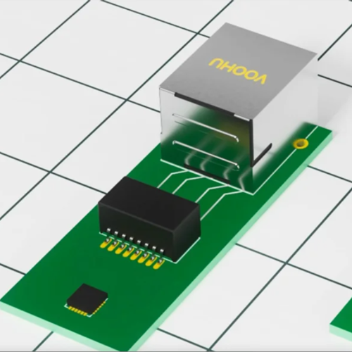
The conduction test measures the power port, but the longest "antenna" on the whole machine is actually the network cable. The common mode current of the network port is large, which will not only be exposed in the radiation (RE) test, but will also flow back through the chassis and ground plane, which in turn will increase the common mode noise floor of the power port. Ensure when designingGigabit network transformerThe common mode rejection ratio (CMRR) is better than -40dB at 100MHz, Bob Smith termination is complete (75Ω + 1000pF/2kV to chassis ground); for multi-gigabit, industrial or automotive scenarios, connect in series between PHY and network transformerSignal line common mode inductor(such as WHAC3225B, WHLC2012A), and can usually suppress the common mode noise by another 10~15dB. The transient protection of the power port and network port is completed by the cooperation of bidirectional TVS and GDT.
Conclusion
In the final analysis, the rectification of conduction disturbance at the DC power port consists of three things: first, distinguish between differential mode and common mode, then align the impedance peak of the device to the super-standard frequency band, and finally return to the source to reduce dv/dt and high-frequency loop area. Choosing the right common mode inductor and replacing it with the right power inductor often saves money and board space than adding three-stage filtering afterwards, and it is also easier to test in one go.
VOOHU provides one-stop on-shelf supply and selection support from power line common mode inductors, integrated inductors, signal line common mode inductors, to network transformers, integrated magnetic RJ45 and ESD/TVS/GDT protection devices, with complete parameters, stable delivery, and fast samples - leaving design margin for performance and leaving uncertainty to a reliable supply chain. For more network equipment power and interface solutions, please visitVOOHU data communication application page, or contact our technical support team for impedance curves and selection recommendations.
Frequently Asked Questions (FAQ)
Q1. If the conduction exceeds the standard by 10dB, should I replace the common mode inductor or add a Y capacitor first?
Be sure first before taking action. If it is a wide envelope of 5~30MHz (common mode dominant), adding a Y capacitor (2×2.2nF to chassis ground) can usually get 6~12dB immediately and at the lowest cost; if it is a peak of 150kHz~2MHz (differential mode dominant), adding a Y capacitor is almost ineffective. The X capacitor should be increased to 2.2μF and a common mode inductor with a larger leakage inductance should be selected. Replacing the inductor without making a judgment is the least efficient path to rectification.
Q2. How does the "1000Ω@100MHz" in the specification correspond to my over-standard frequency?
That's just a nominal point on the impedance curve, what really determines the effect is where the impedance peak (self-resonant frequency) falls. Rule of thumb: The larger the nominal impedance value, the higher the sensitivity, and the peak value is closer to the lower frequency. If 8MHz exceeds the standard, it is recommended to choose the 600~1000Ω range (such as WHAL-9070A-601T0 / -102T0); if 500kHz exceeds the standard, choose the 2200~3000Ω range (such as WHAL-1513A-222T0). When in doubt, asking VOOHU for a measured impedance curve is much more reliable than looking at a single point value.
Q3. Can the rated current be selected based on the average input current?
Can't. A margin of 30%~50% should be left based on the maximum input current, and the drop in inductance caused by DC bias should be considered (Lcm may only be 50%~70% at full load). For a 54V/2.5A PoE switch, it is recommended to choose a model with a rated current ≥3.5A; also check the rated voltage level. The VOOHU power line common mode inductor has three levels of 50V/80V/125V, and the 48V/54V system must use the 125V level.
Q4. Can magnetic beads be used instead of common mode inductors to reduce costs?
Not recommended. The differential mode magnetic beads on the power line are mainly effective above 30MHz and have little contribution to the conduction disturbance from 150kHz to 10MHz. Moreover, the saturation is serious under high current, and the DC voltage drop and temperature rise are not good-looking. The real cost reduction space lies in choosing the right impedance level and avoiding "over-designed" two-stage filtering, rather than replacing CMC with magnetic beads.
Q5. How helpful is the integrated inductor to EMI?
Compared with wound inductors with open magnetic circuits, the one-piece inductor has a closed magnetic circuit and small magnetic leakage, which can significantly reduce the near-field coupling between the input line and adjacent wiring. The overall improvement of 3~6dB is common in actual measurements, while the DCR is lower and the temperature rise is smaller. When selecting a model, leave a margin for ISAT ≥ 1.3×peak current and IRMS ≥ 1.2×rms current. For example, for a 5V/5A output Buck, it is recommended to start with the WHYT1050 grade.
Q6. Can the Y capacitance be continuously increased?
cannot. Y capacitance is limited by leakage current (information class I equipment usually requires ≤3.5mA, medical equipment is more stringent), and DC input equipment generally takes 2×2.2nF~4.7nF. After the common mode is reached, you should switch to two-stage common mode filtering, increase the impedance of the common mode inductor, or improve the grounding, instead of continuing to pile up Y capacitors.
Q7. What should I do if the radiation (RE) exceeds the standard after conduction?
First use a current clamp to measure the common mode current of the cable - the cable is the main radiation source. The countermeasures are: connect the signal line common mode inductor (such as WHAC3225B) in series to the network port, confirm that the network transformer CMRR and Bob Smith termination are complete, make a low-impedance multi-point connection between the chassis ground and the PCB reference ground, and make a 360° overlap for the shielding layer. The power port filter only solves the problem of conduction, and the common mode current of the cable is the main cause of radiation.