Detailed explanation of VOOHU: PoE switch (PSE side) multi-port network port design - multi-port integrated magnetic RJ45, network transformer bias and port crosstalk/heat dissipation pit avoidance
Detailed explanation of VOOHU: PoE switch (PSE side) multi-port network port design - multi-port integrated magnetic RJ45, network transformer bias and port crosstalk/heat dissipation pit avoidance
Introduction: Why does the 8-port PoE switch always overturn when "full load power supply"
PoE switches seem to be one of the easiest boards to make—copy and paste a Gigabit network port eight or sixteen times, then connect the switching chip and you're done. However, engineers who have actually done PSE (power supply equipment) side design all know that this board is the most prone to overturning during the research and development stage: when no load is used, the eight ports negotiate Gigabit and everything is normal. Once eight IP cameras, wireless APs or access control equipment are connected at the same time and PoE is powered at full power, problems will occur - individually The port speed is randomly reduced to 100 Mbit/s, and the packet loss rate increases significantly with long cables; the network port area is hot to the touch, and the temperature rise approaches the upper limit of the device after running at full load for two hours; during the EMC radiated emission test, the noise peak occurs exactly in the port-dense area; when thunderstorms arrive, a common mode surge often knocks out not one port, but an entire row.
What these failures have in common is that the root cause cannot be found at the software and protocol layers, and ultimately all fall back to the magnetic components, termination networks, protective devices and PCB layout of the physical layer. The more critical point is often overlooked - the PSE port and the PD (powered device) port seem to be "network ports with PoE", but in engineering they are two different things: a board on the PD side usually has only one power receiving port, while the PSE side requires eight to twenty-four ports side by side on the same PCB, and each port must superimpose a continuous DC power supply current on top of the Gigabit differential signal. When the number is large, magnetic bias, crosstalk, heat and surge are all amplified according to the number of ports.
Technical Analysis: Five Physical Layer Truths about PSE Ports
1. DC bias: The PSE side is under "normal pressure", not an occasional working condition
Power over Ethernet is injected into DC through the center tap of the network transformer: Alternative A uses 1/2 and 3/6 line pairs, Alternative B uses 4/5 and 7/8 line pairs, and 802.3bt uses four pairs of power supplies at the same time. When DC current flows through the transformer winding, a static magnetic field will be generated in the magnetic core, pushing the operating point of the magnetic core from the midpoint of the B-H curve to the bias point. The equivalent result is that the open circuit inductance (OCL) decreases. Once the OCL drops, the impedance of the transformer in the low frequency band (100kHz~1MHz) will also decrease. The most direct consequence is that the return loss of 1000BASE-T is unqualified at the low frequency end, the differential output voltage template (Template) is too poor, and the signal-to-noise margin of the link is eaten up. This is manifested in the system as "the negotiation fails to reach Gigabit, and it automatically drops to 100M" and "packets are lost under long cables, and the bit error rate increases."
What should be paid attention to in engineering is the current of each pair of wires: 802.3af has about 350mA per pair; 802.3at (PoE+, 30W) has two pairs of power supply, each pair has about 600mA; 802.3bt Type 3 (60W) has four pairs of power supply, each pair has a maximum power supply of about 600mA; Type 4 (90W) has four pairs of power supply, and each pair has a maximum power supply of about 960mA~1A. The selection rules are simple: the PoE rated bias current of the network transformer must be no less than the maximum current of each pair of ports, with a margin of 30% to 50%; at the same time, be sure to confirm that the OCL given by the manufacturer is the minimum value "with bias current", not a beautiful number under no PoE conditions. Many cases of "good prototypes but slowdown in mass production" are rooted in this margin.
2. Multi-port integrated magnetic RJ45 vs discrete network transformer: What you save is area, but what you pay for is heat dissipation and crosstalk.
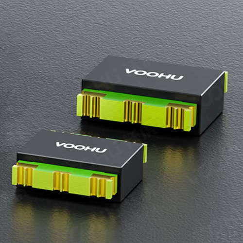
The most typical choice on the PSE side is to use multiple ports such as 2x4 and 1x8Integrated magnetic RJ45 connector(SYT series, the network transformer and common mode choke are inserted into the connector), or useDiscrete Gigabit Network Transformer(WHSG single port, WHDG dual port) plus pure RJ45 connector. The advantages of the integrated solution are clear: the PCB area is greatly saved, the length of the differential wiring from the connector to the PHY is greatly shortened, the port consistency and panel neatness are good, and the production line mounting and inventory are simple. It is especially suitable for 8-port/16-port desktop and consumer-grade PoE switches.
The price is equally clear. The first is heat dissipation: the magnetic parts are sealed in a plastic case, and the I²R loss of the winding cannot be dissipated. The hot spots of the eight-port module will be superimposed. When PoE is fully loaded, the internal temperature rise is often 10~20°C higher than that of the discrete solution. The second is isolation between ports: the internal differential pair spacing of the multi-port module is compressed, and the port-to-port crosstalk (NEXT/PSANEXT) and surge crosstalk paths are shorter. Third, optional specifications are limited: the PoE current level, Hi-Pot withstand voltage (commonly 1500Vrms) and operating temperature ranges of integrated modules are not as rich as those of discrete components. Therefore, our empirical criteria are: non-PoE or PoE+ (≤30W), number of ports ≤16, consumer/commercial desktop scenarios, priority is given to integrating magnetic RJ45; PoE++ (802.3bt Type 3/Type 4, 60W/90W), industrial or outdoor, wide temperature range - 40~+105℃, and scenarios requiring isolation above 2.25kV. Priority should be given to discrete network transformers and independent connectors to disperse the heat source and select sufficient specifications.
3. Inter-port crosstalk and Bob Smith termination: the most common is "shared termination"
The most frequent schematic error on multi-port boards is to merge the Bob Smith termination networks of multiple ports: eight ports share a 1000pF/2kV capacitor connected to the chassis ground, or the 75Ω terminals of each port are connected to the same node. This saves a few materials, but forcibly connects the common-mode loops of the eight ports together - the common-mode noise and surge energy on one port will be directly transmitted to the adjacent ports, worsening the NEXT and increasing the radiated emission. The phenomenon of "breaking one port and damaging the entire row" during surge testing is mostly caused by this. The correct approach is to have an independent Bob Smith network for each port: four channels of 75Ω (or the value recommended in the transformer data manual) are connected to a node of this port, and then connected to the chassis ground at a single point through the port's own 1000pF/2kV high-voltage capacitor; the metal shell that shields the RJ45 is also grounded at a single point according to the port to avoid forming a low-resistance common mode path between the ports.
There are three hard rules for layout: differential pairs must be of exactly the same length, internal deviations should be controlled within a reasonable range, and 100Ω differential impedance should be maintained between lines; the reference plane under the transformer (or integrated RJ45) should be treated with an isolation zone to clearly separate the "cable side" from the "system side"; the traces in the port area should not pass directly under the magnetic parts of other ports, otherwise no matter how good the device is, it will not be able to save the coupling caused by the layout.
4. Lightning surge: The PSE port must protect not only the PHY, but also the PSE controller and MOSFET.
The PSE port is connected to an external cable with a length of tens or even hundreds of meters, and common mode surges caused by lightning induction are commonplace. The safe approach is still to use three levels of cooperation: the first level usesGas discharge tube GDT(such as WHGD090V1P0B, 90V DC breakdown) performs line-to-ground discharge to conduct the kilovolt-level common mode energy away before entering the transformer; the second stage relies on the isolation withstand voltage of the network transformer itself (1.5kV~4kV Hi-Pot) to bear the remaining common mode voltage; the third stage is used on the center tap and PoE power supply rail sideTwo-way TVS(such as WHTB058VA, 58V level) clamping - this level is particularly important on the PSE side, because the PSE controller and power MOSFET on the 48V/57V power rail are more expensive and more fragile than the PHY. When the surge pours into the power rail along the center tap, they are often the first to be penetrated. A low-capacity ESD array is added to the PHY side to withstand contact discharge caused by plugging and unplugging. Protection devices must be configured independently for each port. Sharing will reopen the crosstalk path that was just isolated. If you need a ready-made reference circuit, you can directly use VOOHU'sPoE solution pageOutdoor 4kV/6kV lightning protection reference design in (distinguish between voltage type and current type PHY).
5. Thermal and power budget: I²R is the invisible killer
Many people only calculate the output power budget of the PSE: eight ports × 30W = 240W, and select 300W for the power supply. What really causes the temperature rise in the port area to get out of control are the invisible I²R losses. Taking 802.3bt Type 3 as an example, each pair of wires has 600mA, and one port provides four pairs of power supply. If the DC resistance (DCR) of each winding of the network transformer is of the order of 0.6Ω, the copper loss on the magnetic parts alone is close to 0.9W. The superimposition of eight ports means that about 7W of heat is concentrated in a few square centimeters on one side of the panel. Taking into account the conduction loss of the PSE MOSFET and the heating of the detection resistor, the hot spot temperature easily exceeds 85°C. There are three countermeasures: choose a network transformer with low DCR and an operating temperature level of at least -40~+85°C (industrial and outdoor recommendations -40~+105°C); prioritize using discrete network transformers for high-power ports to separate the heat sources on the PCB; retain a complete copper foil and via array under the magnetic parts and PSE power devices, and use air ducts to dissipate heat.
Solution: VOOHU PSE port selection recommendations
Putting the above five items onto the material number, the selection on the PSE side can actually be made into a quick reference list. The exchange master can use VOOHU proxyEthernet switching chip(For example, JL5108C -2.5G/5G BASE-T network transformer(WHSQ/WHDQ series). The following table provides recommended combinations of magnetic components and protection configurations based on typical port scenarios:
| Port scenario | Rate / PoE level | Maximum current per pair | Magnetic parts solution | VOOHU on-shelf material number/series | Port protection configuration |
|---|---|---|---|---|---|
| 8-port desktop switch (non-PoE) | 1000BASE-T/non-PoE | — | Multi-port integrated magnetic RJ45 (2x4/1x8) | SYT series (such as SYT811B198FA2A10DQB) | ESD array + independent Bob Smith termination for each port |
| 8/16-port PoE+ switch (30W) | 1000BASE-T/802.3at | ≈600mA | Integrated magnetic RJ45 (PoE 600mA level) or discrete network transformer | SYT series (600mA) / WHSG24301JM, WHSG24701D1 | GDT WHGD090V1P0B + Bidirectional TVS WHTB058VA |
| 16/24-port PoE++ switch (60W) | 1000BASE-T/802.3bt Type 3 | ≤600mA | Discrete network transformer + independent RJ45 (heat source dispersed) | WHSG24R03D0 (single port)/WHDG48201P1 (dual port) | GDT per port + bidirectional TVS on power supply rail + ESD on PHY side |
| Industrial/Outdoor PSE (90W) | 1000BASE-T/802.3bt Type 4 | ≤960mA | Discrete network transformer, ≥1000mA bias, -40~+105℃ | WHSG series (1000/1500mA, 2.25~4kV specifications) | GDT + TVS + ESD level 3, independent ports |
| 2.5G/5G uplink port | 2.5G/5GBASE-T | by bt level | 2.5G/5G dedicated network transformer (low insertion loss, high CMRR) | WHSQ24015P1/WHDQ96504P2 | Low-capacity ESD array (≤0.5pF) |
| Exchange master and PHY | 8×GE + 2×2.5G uplink | — | — | JL5108C-NC / JL6110-PC | — |
There are two details that are easily overlooked when selecting a model. First, the PoE current level of the integrated magnetic RJ45 should be selected based on the "maximum power level of the port" rather than the "typical load": it is normal for on-site users to replace a 30W dome camera with a 60W PTZ machine. Second, the Hi-Pot withstand voltage of the network transformer must be aligned with the safety requirements of the entire machine: 1500Vrms is usually sufficient for indoor desktop switches, but for outdoor PSE or industrial scenarios in the same cabinet with strong power, 2.25kV or even 4kV specifications should be directly selected, and combined with GDT to form a complete discharge path.
Conclusion: Incorporate the reliability of the PSE port into device selection
The essence of the PSE port design of PoE switches is to make a systematic balance in the five dimensions of "signal integrity - power supply capability - protection level - heat - cost", and the final point of this balance is the specific models of magnetic components, connectors and protective devices. Calculate the bias current of each pair of lines clearly, leave enough margin according to the maximum power level, decide whether to integrate or separate based on the number of ports and power density, insist on independent termination and level 3 protection for each port, and then spread the heat on the PCB - if these four things are done in place, the probability of the port passing the conformance test, EMC and surge certification will be significantly improved, and a lot of time for later rectification and rework can be saved.
VOOHU's full-rate network transformers from 10/100M to 18G BASE-T, SYT series multi-port integrated magnetic RJ45, GDT/TVS/ESD protection devices to Ethernet PHY and switching chips can complete the entire link selection of PSE ports on one platform, and provide OCL with bias conditions, return loss and CMRR measured data as well as reference PCB layout. If you have any questions about the selection, please send us the number of ports, PoE level, speed and certification requirements, so that each network port can be reliable, stable and mass-produced.
Frequently Asked Questions (FAQ)
Q1. After the PoE is fully loaded, the Gigabit link drops to 100 Mbit/s. Is it necessarily a problem with the network transformer?
Not necessarily, but Internet changes are the first suspect. First turn off PoE and retest: If Gigabit is stable after turning off PoE, but slows down when turning on PoE, it can be basically determined that the DC bias causes the OCL to decrease and the low-frequency return loss exceeds the standard; if the speed still slows down after turning off PoE, you should check the differential pair impedance and equal length, Bob Smith termination, and matching resistor on the PHY side.
Q2. Should the PoE current of the network transformer be calculated based on the total power of the port, or based on the current of each pair of lines?
Calculated based on the maximum current of each pair of wires. 802.3af is about 350mA/pair, 802.3at (30W) is about 600mA/pair, 802.3bt Type 3 (60W) is up to about 600mA/pair when four pairs are powered, and Type 4 (90W) is up to about 960mA~1A/pair. The PoE rated bias current of the network transformer should not be lower than this value, with a 30% to 50% margin.
Q3. For an 8-port PoE switch, should one multi-port integrated magnetic RJ45 be used or 8 discrete network switches?
Depends on power density and usage environment. Non-PoE or PoE+ (≤30W), number of ports ≤16, consumer/commercial desktop products, priority is given to multi-port integrated magnetic RJ45, saving area and wiring; PoE++ (60W/90W), industrial or outdoor, requiring isolation of 40~+105℃ or 2.25kV or above, priority is given to discrete network converters and independent RJ45 to disperse the heat source and select sufficient specifications.
Q4. Can multiple ports share a high-voltage capacitor with Bob Smith termination?
Not recommended. Common termination will connect the common mode loops of each port together, causing noise and surge energy to flow between the ports, worsening NEXT and increasing radiated emissions. In surge testing, "one port will damage the entire row" often occurs. The correct approach is to have an independent 75Ω×4 termination for each port, and connect it to the chassis ground at a single point through its own 1000pF/2kV capacitor.
Q5. How many levels of surge protection should be required for the PSE port? How to choose TVS voltage?
Three levels are recommended for outdoor or long cable scenarios: line-to-ground GDT (such as WHGD090V1P0B, 90V DC breakdown) to discharge the main energy; the 1.5kV~4kV isolation of the network transformer bears the residual common mode voltage; the center tap and the PoE power supply rail side are clamped with a bidirectional TVS (such as 58V-level WHTB058VA) to protect the PSE controller and power MOSFET; the PHY side is supplemented with a low-capacitance ESD array.
Q6. If the temperature in the network port area rises, can it be solved by changing to a more powerful power supply?
cannot. The temperature rise mainly comes from the local I²R loss of the port - the copper loss of the network transformer winding, the conduction loss of the PSE MOSFET and the heating of the detection resistor, and has nothing to do with the power supply margin. Network transformers with low DCR and -40~+85℃ (industry recommendation -40~+105℃) should be selected; high-power ports should use discrete network transformers to dissipate heat sources, and retain copper foil and via arrays under the devices to cooperate with air ducts for heat dissipation.
Q7. Can the 2.5G/5G uplink port continue to use a Gigabit network transformer?
Not recommended. 2.5G/5GBASE-T has stricter requirements for insertion loss and return loss. Gigabit network converters have insufficient margin in high frequency bands and are prone to link instability or bit errors. The uplink port should select a 2.5G/5G dedicated network transformer (such as WHSQ24015P1, WHDQ96504P2) and be equipped with a low-capacity (≤0.5pF) ESD array to avoid capacitive loads from degrading signal integrity.