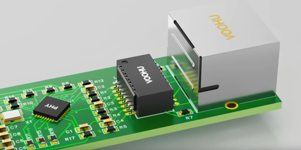
VOOHU actual combat: What do you think of the network transformer data manual? Interpretation of the five major parameters of OCL/insertion loss/return loss/common mode suppression/DCR and selection and pitfall avoidance
VOOHU actual combat: What do you think of the network transformer data manual? Interpretation of the five major parameters of OCL/insertion loss/return loss/common mode suppression/DCR and selection and pitfall avoidance
When choosing a network transformer (network transformer), many engineers only look at three things: speed (100M/100M/2.5G), packaging (SMD or direct plug, single port or multi-port) and PoE current. Once the material number is filled in, the schematic diagram is passed. The trouble begins when the prototype enters the laboratory: the link cannot be negotiated or is inexplicably slowed down, packets are lost as soon as the long network cable is connected, radiated emission (RE) peaks at 30~300MHz, the network port becomes hot after half an hour of full load... A search at the software level often cannot find the root cause, and in the end it is found that the fault falls on the "randomly selected" network transformer.
The root of the problem lies in the 8 to 10 electrical parameters in the network transformer data manual. Most people only glance at the speed and withstand voltage, and skip the rest. What really determines whether a network port can be tested in one go is precisely the ones that are skipped. This article explains the five most critical parameters in the network transformer manual - open circuit inductance OCL, insertion loss, return loss, common mode rejection ratio CMRR, and DC resistance DCR - one by one: what they are, what kind of fault will appear on the test bench if the parameters are not up to standard, how to read the numbers in the manual, and finally provide a selection quick check sheet based on the shelf material number of VOOHU (VOOHU).
1. First understand what the network changer does in the network port.
To define the role of the network transformer in one sentence: The essence of the Ethernet network transformer is a combination of 1CT:1CT high-frequency isolation transformer + common mode choke. It couples the PHY's differential signals to the cable side in isolation while providing approximately 100Ω impedance matching, isolation withstand voltage, and common-mode noise rejection. Precisely because it plays the roles of "signal path" and "electromagnetic barrier" at the same time, the parameters in the data sheet have both signal integrity (SI) items and EMC items.
The following five parameters cover these two main lines: OCL and turns ratio, insertion loss, and return loss tubes refer to "whether the signal can be transmitted cleanly"; CMRR, DCR and crosstalk tubes refer to "whether they will radiate outwards, generate heat, and whether multiple ports will fight each other." Once you understand these five numbers, network change selection will change from "guessing" to "calculating".
2. Dismantling the five key parameters one by one: the fault behind the numbers
① Open-circuit inductance OCL and turns ratio - determine the low-frequency response and whether it will be saturated under PoE
Open Circuit Inductance (OCL) is the inductance of the primary winding when the secondary is open. Typical test conditions are 100mV, 100kHz, and about 8mA DC bias is superimposed. The common lower limit for gigabit is 350µH. OCL determines the low-frequency turning point of network transformation: 1000BASE-T uses PAM-5 line code, which contains rich low-frequency components. Low OCL will cause insufficient coupling of low-frequency signals, manifesting as baseline wander, eye diagram closure, handshake failure, or direct slowdown to 100 Mbit/s.
Even more hidden is PoE: when powered, DC current flows through the winding through the center tap, the core is biased by DC, and the equivalent OCL decreases or even saturates. Therefore, when building a PoE network port, be sure to look at the column "OCL with DC bias" instead of the no-load value - this is why VOOHU's 100/1000 BASE-T Gigabit Network Transformer There will be a distinction between ordinary models and PoE high current models. In terms of turns ratio, most voltage-driven PHYs use 1:1 (1CT:1CT); a few current-driven PHYs require 1:1.41 or 2:1. Choosing the wrong turns ratio will directly lead to incorrect signal amplitude and abnormal negotiation.
② Insertion Loss - directly eats up your signal-to-noise margin
Insertion loss is a measure of how much energy a signal loses as it passes through the network, in dB (negative values, closer to 0 is better). The typical requirement for Gigabit network transformers is no worse than about −1.0dB within 1~100MHz. Don’t underestimate this 1dB: it is directly deducted from eye height and signal-to-noise ratio (SNR). It cannot be seen when the cable is short. Once it is connected to a long cable of 80~100m or old Cat5e, the insertion loss, cable loss, and crosstalk will squeeze the margin together, resulting in packet loss and increased bit error rate in the long-term compatibility test. When selecting a model, the flatter and lower the insertion loss curve, the better. Pay special attention to whether the high frequency band (60~100MHz) is tilted.
③ Return Loss - If the impedance does not match, it will be reflected. The consistency test will directly determine Fail.
Return loss reflects the matching degree of the network transformer port impedance and the 100Ω system impedance. The larger the absolute value, the better. Common requirements for Gigabit: ≥16~18dB within 1~30MHz, gradually relaxed to about 12dB at 40~80MHz. Impedance mismatch will produce reflections, which can cause direct failure in the consistency test (Return Loss Mask), or superimpose cable reflections to increase the bit error rate and prevent high-speed negotiation. Return loss is related to the PCB differential trace impedance, the leakage inductance and parasitic capacitance of the network transformer itself - the RL curve in the manual is the "upper limit that the device can provide", and poor wiring will only make things worse.
④ Common mode rejection ratio CMRR - the winner of network port radiation and interference immunity
Common Mode Rejection Ratio (CMRR) measures the network transformer's ability to suppress common mode noise and is the most critical EMC item. An ideal differential signal does not generate common mode current, but the timing skew of the PHY output, the asymmetry of the wiring, and the asymmetry of the network transformer itself will all convert part of the differential mode energy into common mode (mode conversion). When the common mode current runs to the cable, it becomes an antenna, which directly causes the radiated emission (RE) to exceed the standard at 30~300MHz.
Network transformers with good CMRR (such as typical −35dB@1~30MHz) can suppress this part of the common mode; when the CMRR margin is not enough, external Signal line common mode inductor Do secondary suppression. On the other hand, CMRR also determines the interference immunity: whether external common-mode interference can be blocked from the PHY. Therefore, when radiated emissions cannot be corrected repeatedly, or there are requirements for immunity after lightning surges, CMRR is the first parameter to be checked.
⑤ DC resistance DCR, crosstalk and isolation withstand voltage - temperature rise, PoE voltage drop and multi-port isolation
DC resistance (DCR) is the ohmic resistance of the winding, typically ≤0.9Ω per winding. The larger the DCR, the greater the voltage drop and I²R heat generated when PoE current flows. This is one of the common sources of "hot network ports at full load"; multi-port network changes also add heat dissipation pressure caused by port density. Crosstalk (Crosstalk) is particularly important in multi-port or multi-connected integrated RJ45. The typical crosstalk requirement between ports is ≤-35dB. The more negative, the better. If it is too bad, adjacent ports will interfere with each other and cause packet loss. The isolation withstand voltage (Hi-Pot, Vt) is usually 1500Vrms. For outdoor or industrial scenarios, the 3kV/4kV reinforced isolation model should be selected.
3. Solution: Five-step manual reading method + full rate selection
Match the above five parameters with the application, and the selection will be organized. Give engineers a "five-step manual reading method": ① First lock the series according to the rate (10/100, Gigabit, 2.5G/5G, 10G); ② To determine whether PoE, PoE, check "OCL with DC bias" and PoE current level; ③ Compared with the insertion loss and return loss curve, long-line or high-speed scenarios give priority to low insertion loss and high return loss; ④ According to the EMC target CMRR, add the signal line common mode inductor for serious radiation; ⑤ Finally check DCR, crosstalk, isolation withstand voltage and operating temperature.
Falling to the material number, VOOHU (VOOHU) provides from 10/100 BASE-TX Network Transformer, Gigabit, to 2.5G/5G BASE-T Multi-Gigabit Network Transformer with 10G BASE-T 10G network transformer full rate network change, and SYT Series Integrated Magnetic RJ45, the parameter bandwidth and PoE range are complete; in tight space or multi-port scenarios, you can directly use the integrated model to save area, shorten wiring, and improve consistency. The following quick reference table lists common speed parameter concerns together with the on-shelf material numbers to facilitate quick alignment of requirements (the material numbers in the table are in plain text, and detailed parameters are subject to the data manual on the corresponding product page).
Table: VOOHU full-rate network transformer/integrated RJ45 key parameters and quick check of on-shelf material numbers
| rate/type | Represents the item number on shelf | Key parameter concerns (typical) | Typical applications |
|---|---|---|---|
| 10/100BASE-TX | 10/100 network transformer series / SYT integrated RJ45 | OCL≥350µH; insertion loss≤−1.1dB; CMRR≥−30dB; Vt 1.5kV | 100M network port, IoT, set-top box |
| 100/1000 BASE-T (Gigabit) | WHSG24701D1/WHDG48201P1 | Bias OCL≥350µH@8mA; insertion loss≤−1.0dB@1~100MHz; return loss≥16~18dB; CMRR≥−35dB | Switch/Router/Gateway Gigabit Port |
| 2.5G/5G BASE-T | WHSQ48002P1/WHDQ96504P2 | Bandwidth to 100~200MHz; low insertion loss; return loss ≥14~16dB | Multi-gigabit uplink/wireless AP backhaul |
| 10GBASE-T | WHSM24702N0/WHSM24002G | Bandwidth to 400~500MHz; extremely low insertion loss, high return loss; strict control of crosstalk | Server / 10G switching / NAS |
| PoE/PoE+ port | WHSG…P / WHSQ…P (PoE special model) | Bias OCL meets standard; low DCR; PoE current 350mA~1.5A | PoE camera/AP/PSE port |
| Integrated magnetic RJ45 | SYT111B372EA2A1DFL/SYT811B198FA2A10DQB | Network transformer + RJ45 integrated; good parameter consistency; saving area | Multi-port switch/space tight model |
| Signal line common mode inductor (supplementary) | WHAC3225B/WHLC2012A | Improved CMRR, reduced common mode current; small differential mode insertion loss | RE rectification/anti-interference tightening |
4. Conclusion
The network converter seems to be just an inconspicuous "magnetic piece" on the network port, but it also stresses the two lifebloods of signal integrity and EMC. Instead of waiting for the prototype to roll over repeatedly in the laboratory and modify the board again and again, it is better to understand the five numbers of OCL (especially under PoE bias), insertion loss, return loss, CMRR, and DCR during the selection stage and align them with the application requirements.
By selecting the right parameters, the network port can be tested once and be stable for a long time - this is exactly the "reliability" that VOOHU (VOOHU) wants to help engineers achieve. Full-speed network transformers from 100M to 10G, integrated magnetic RJ45 and matching common-mode inductors can be sampled for evaluation. If the parameters are uncertain, you can directly contact us for selection confirmation to avoid risks before sampling.
Frequently Asked Questions (FAQ)
Q1. How big should the OCL (open circuit inductor) be? Do you want to watch it again under PoE?
The common lower limit of Gigabit network transformer OCL is 350µH (100mV/100kHz). When doing PoE, you must look at the OCL after superimposing DC bias (such as 8mA), not the no-load value - DC bias will cause the equivalent inductance to decrease or even saturate. For PoE/PoE+ ports, it is recommended to choose PoE-specific models (such as WHSG...P series) marked with corresponding PoE current levels to ensure that the OCL still meets the standard under bias.
Q2. How much insertion loss is considered qualified? Does a 1dB difference really have such a big impact?
Gigabit network conversion typical requirements are no worse than about −1.0dB within 1~100MHz. Don’t underestimate 1dB: it is directly derived from eye height and SNR. It cannot be seen on short lines, but on long lines (80~100m) or old Cat5e, the insertion loss superimposed on the line loss and crosstalk will eat up the margin, causing packet loss and bit error rate to increase. It is preferred to choose a material number with a flat and low insertion loss curve and no distortion in the high frequency range.
Q3. If the return loss test fails, what should I check first?
First distinguish whether it is a device or a wiring. The manual RL curve is the upper limit of the device, 1~30MHz should be ≥16~18dB. If the device itself meets the standards, focus on checking whether the differential pair impedance is 100Ω±5%, the network change to RJ45 trace length and symmetry, the center tap capacitor and Bob-Smith termination. In terms of device selection, priority is given to network transformers with low leakage inductance and small parasitic capacitance.
Q4. What is the relationship between CMRR and radiated emission (RE) exceeding the standard?
The higher the common-mode rejection ratio, the lower the common-mode current generated by the network transformer converting differential mode to common mode, the smaller the common-mode current on the cable, and the lower the radiation. RE exceeds the standard at 30~300MHz, which is most likely related to common mode current. First choose a network transformer with good CMRR. If it is not enough, add a signal line common mode inductor (such as WHAC3225B) for secondary suppression.
Q5. How to control port crosstalk when using multi-port network transformers or multi-link integrated RJ45?
Look at the inter-port crosstalk (Crosstalk) indicator in the manual. Typical is ≤−35dB. The more negative the better. When multiple ports are closely packed, attention should also be paid to the heat dissipation caused by DCR. In terms of layout, the differential pairs of each port should be spread as far apart as possible to avoid long-distance parallel coupling; in scenarios sensitive to crosstalk, a single-port network transformer can be used in a discrete layout, or a multi-port material number with better crosstalk indicators can be selected.
Q6. What are the parameters to choose between discrete network transformer and integrated magnetic RJ45 (SYT)?
The electrical parameter system of the two is consistent (OCL, insertion loss, return loss, and CMRR all need to be looked at). The integrated model combines the network transformer, RJ45, and sometimes Bob-Smith, saving area, short wiring, and good consistency, and is suitable for tight space and multiple ports; the discrete model is flexible, easy to optimize network transformers and connectors independently, and helps reduce costs. Under the premise that the parameters meet the standards, the balance should be based on space, cost and maintainability.
Q7. Will DCR cause the network port to become hot? Is it related to PoE?
related. DCR is the winding ohmic resistance, typically ≤0.9Ω/winding. The PoE current flows through the winding through the center tap. The greater the DCR, the greater the voltage drop and I²R heating. The temperature rise is especially obvious when there are multiple ports at full load. For high-current PoE ports, choose low DCR, PoE-specific models, and match copper foil heat dissipation and reasonable port spacing.
Q8. Should I choose 1:1 or non-1:1 for the turns ratio? What is the basis?
Follow the PHY datasheet. The vast majority of voltage-driven PHYs use 1:1 (1CT:1CT); a few current-driven PHYs or specific chips require non-1:1 turns ratios such as 1:1.41 and 2:1. Wrong selection will lead to signal amplitude mismatch and abnormal negotiation. Be sure to check the PHY recommended network transformer turns ratio and termination circuit before selection.