Contact count
Eight for RJ45, four or six for RJ11. The housings differ in width and keying, so an RJ11 plug fits an RJ45 jack but not the reverse.

I/O Connector products
The main RJ45 range covers vertical and right angle PCB jacks, shielded and unshielded, with or without integrated magnetics. Start from the link speed and the panel arrangement, then decide whether the magnetics belong in the connector or on the board.
Part number search & selector
The table uses the current English-site product records, published selection fields and part-specific technical-file links.
* Frozen Image and Part Number columns · drag horizontally to review all specifications
| Image | Datasheet | Compare | Downloads |
Category
|
Connector Type
|
Ports
|
Tab
|
Integrated Connector Modules
|
Data Rate
|
PoE
|
LED
|
Mounting Method
|
Shield Tabs
|
EMI / Gasket
|
Operating Temperature
|
Sample |
|---|
| Image | Part number | Datasheet | Compare | Downloads | Category | Connector Type | Ports | Tab | Integrated Connector Modules | Data Rate | PoE | LED | Mounting Method | Shield Tabs | EMI / Gasket | Operating Temperature | Sample |
|---|---|---|---|---|---|---|---|---|---|---|---|---|---|---|---|---|---|
 |
SYT52221188IWA1DY1 | SPEC | RJ45 Connector | 90° | 1 x 1 | Up | NO | ALL | ALL | NO LED | SMD | NO | NO | -40 to +85°C |
|
||
 |
SYT52F1188IWW5SB4ML078 | SPEC | RJ45 Connector | 180° | 1 x 1 | Up | NO | ALL | ALL | NO LED | SMD | NO | NO | -40 to +85°C |
|
||
 |
SYT52F1188IWA5SB4078 | SPEC | RJ45 Connector | 180° | 1 x 1 | Up | NO | ALL | ALL | NO LED | SMD | NO | NO | -40 to +85°C |
|
||
 |
SYT52F1188GWWA5SB4078 | SPEC | RJ45 Connector | 180° | 1 x 1 | Up | NO | ALL | ALL | NO LED | SMD | YES | NO | -40 to +85°C |
|
||
 |
SYT52D1188IWW6SB3ML162 | SPEC | RJ45 Connector | 180° | 1 x 1 | Up | NO | ALL | ALL | NO LED | SMD | NO | NO | -40 to +85°C |
|
||
 |
SYT52D1188GWA6SB1T2ML475 | SPEC | RJ45 Connector | 180° | 1 x 1 | Up | NO | ALL | ALL | NO LED | SMD | YES | NO | -40 to +85°C |
|
||
 |
SYT52D1188AB1A6SB1075 | SPEC | RJ45 Connector | 90° | 1 x 1 | Up | NO | ALL | ALL | Y/G | SMD | YES | NO | -40 to +85°C |
|
||
 |
SYT211B227DB1A7CBS057 | SPEC | RJ45 Connector | 90° | 1 x 1 | Up | YES | 10/100M | Non-PoE | Y/G | SMD | YES | YES | -40 to +85°C |
|
||
 |
SYT211Q380AA1A7S009 | SPEC | RJ45 Connector | 90° | 1 x 1 | Up | YES | 100/1000M | Non-PoE | Y/G | SMD | YES | NO | -40 to +85°C |
|
||
 |
SYT311B093AA2A7S009 | SPEC | RJ45 Connector | 90° | 1 x 1 | Up | YES | 10/100M | Non-PoE | G/Y | SMD | YES | NO | -40 to +85°C |
|
||
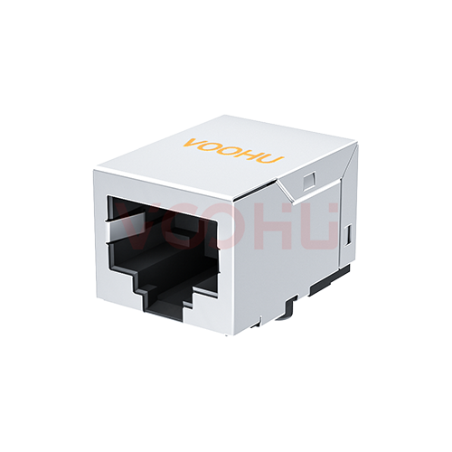 |
SYT111B002GWA7S | SPEC | RJ45 Connector | 90° | 1 x 1 | Down | YES | 10/100M | Non-PoE | NO LED | SMD | YES | NO | -40 to +85°C |
|
||
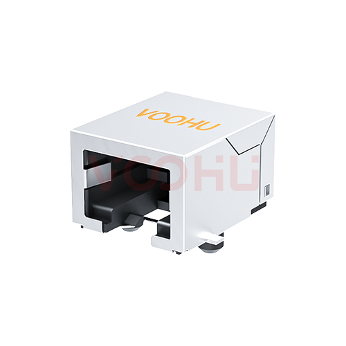 |
SYT56T1118GWA5SB4078 | SPEC | RJ45 Connector | 90° | 1 x 1 | Down | NO | ALL | ALL | NO LED | SMD | YES | NO | -40 to +85°C |
|
||
 |
SYT561188GWA6SB1133 | SPEC | RJ45 Connector | 90° | 1 x 1 | Up | NO | ALL | ALL | NO LED | SMD | YES | NO | -40 to +85°C |
|
||
 |
SYT561188AB1A6SB1133 | SPEC | RJ45 Connector | 90° | 1 x 1 | Up | NO | ALL | ALL | Y/G | SMD | YES | NO | -40 to +85°C |
|
||
 |
SYT52F1188GWWA5SB4ML078 | SPEC | RJ45 Connector | 180° | 1 x 1 | Up | NO | ALL | ALL | NO LED | SMD | YES | NO | -40 to +85°C |
|
||
 |
SYT52D1188AB2A6SB1075 | SPEC | RJ45 Connector | 180° | 1 x 1 | Up | NO | ALL | ALL | G/Y | SMD | YES | NO | -40 to +85°C |
|
||
 |
SYT52D1188GWA6SB1TML075 | SPEC | RJ45 Connector | 180° | 1 x 1 | Up | NO | ALL | ALL | NO LED | SMD | YES | NO | -40 to +85°C |
|
||
 |
SYT52D1188IWW6SB3009 | SPEC | RJ45 Connector | 180° | 1 x 1 | Up | NO | ALL | ALL | NO LED | SMD | NO | NO | -40 to +85°C |
|
||
 |
SYT211B488GWA7CBST6359 | SPEC | RJ45 Connector | 90° | 1 x 1 | Up | YES | 10/100M | 600mA | NO LED | SMD | YES | NO | -40 to +85°C |
|
Broaden the selected filters or clear the current search.
By type
RJ45, RJ11, offset and low height variants, combination housings and dust plugs.
How to select
Contact count, then orientation and height, then shielding, then magnetics.
RJ45 uses eight contacts for Ethernet, often written 8P8C. RJ11 uses four or six for telephony and low speed serial. They are not interchangeable.
Vertical, right angle or offset, depending on whether the cable enters the panel horizontally and where the board sits behind it.
Low height variants exist for slim assemblies. Confirm the clearance above the board as well as the panel cutout before selecting.
Shielded housings help emissions and need a defined chassis path. Integrated magnetics save board area but fix the transformer choice.
Parameters
Contact count and mounting orientation decide fit; shielding decides emissions.
Eight for RJ45, four or six for RJ11. The housings differ in width and keying, so an RJ11 plug fits an RJ45 jack but not the reverse.
Vertical, right angle or offset. Offset variants shift the opening relative to the board so the panel cutout can sit at a different height.
Through hole gives mechanical strength for repeated plugging. Surface mount suits automated assembly but usually needs additional retention.
Low profile variants reduce the clearance needed above the board. Confirm both the body height and the panel cutout position together.
A shielded housing gives the cable screen a path to chassis. It needs a defined ground connection on the board to be effective.
Some RJ45 housings contain the LAN transformer. That saves board area but fixes the magnetics specification inside the connector.
Compare
Contact count and mechanical keying separate what looks like one family.
Return to the selector ↑| Category | Parts | Connector Type | Ports | Tab | Integrated Connector Modules | Data Rate | PoE | LED | Mounting Method | Shield Tabs | EMI / Gasket | Operating Temperature | Action |
|---|---|---|---|---|---|---|---|---|---|---|---|---|---|
| RJ11 Connector | 37 | 90°, 180° | 1 x 1, 1 x 2, 1 x 4, 2 x 1 | Up/Down, up/down, Down, Up | NO | ALL | Non-PoE, ALL | NO LED | DIP | YES, NO | NO | -40 to +85°C | Filter → |
| RJ45 Connector | 627 | 45°, 90°, 180° | 1 x 1, 1 x 2, 1 x 3, 1 x 4, 1 x 5, 1 x 6, 1 x 8, 2 x 1, 2 x 2, 2 x 3, 2 x 4, 2 x 5, 2 x 6, 2 x 8 | Up/Down, up/down, Down, Up, Not specified | YES, NO | ALL, 10/100M, 100/1000M, 2.5G Base-T, 5G Base-T, 10G Base-T, 10/100M +SPD, 100/1000M +SPD | Non-PoE, 350mA, 600mA, 720mA, 900mA, 850mA, 1000mA, 1.5A, ALL, Not specified | NO LED, G/-, G/G, G/Y, G/O, G/GO, G/GY, GO/Y, GO/G, GY/Y, GY/G, GY/YG, GY/GY, GR/GG, GO/GO, GR/GR, GG/RG, OG/Y, Y/G, Y/GY, Y/GO, YG/G, YG/YG, -/G | DIP, SMD, Not specified | YES, NO | YES, NO | 0 to +70°C, -20 to +70°C, -40 to +85°C, -40 to +105°C | Filter → |
| RJ45 Offset Connector | 46 | 90° | 1 x 1, 1 x 4 | Down, Up | YES, NO | ALL, 10/100M, 100/1000M, 2.5G Base-T, 10G Base-T | Non-PoE, ALL | NO LED, G/Y, G/GY, GO/Y, GO/G, O/G, Y/G, Y/GO | DIP, SMD | YES, NO | YES, NO | 0 to +70°C, -40 to +85°C | Filter → |
| RJ45(Low Height) | 29 | 90° | 1 x 1 | Up/Down, Down, Up | YES, NO | ALL, 10/100M, 100/1000M, 5G Base-T, 10G Base-T | Non-PoE, ALL | NO LED, G/Y, GO/Y, GY/Y, GY/G, OG/Y, Y/G, YG/G | DIP | YES, NO | YES, NO | -40 to +85°C | Filter → |
| RJ45 Combination | 32 | 90° | 1 x 1 | Up | YES, NO | ALL, 10/100M, 100/1000M, 2.5G Base-T, 5G Base-T, 10G Base-T | Non-PoE, ALL | NO LED, G/Y, G/GY, GO/Y, GY/G, OG/Y, Y/G, Y/OG, Y/GO | DIP | YES | YES, NO | -40 to +85°C | Filter → |
| RJ45 Dust Plug | 2 | 180° | 1 x 1 | Not specified | NO | - | - | NO LED, - | Not specified | NO | NO | -10 to +85°C, Not specified | Filter → |
| RJ45 combined | 1 | 90° | 1 x 1 | Up | YES | Not specified | Non-PoE | G/Y | DIP | YES | YES | -40 to +85°C | Filter → |
Application review
Confirm the link speed, the panel arrangement and the height available on the board.
Documents
Drawings carry the footprint, panel cutout, retention and recommended hole sizes.
Showing representative available file sets. Search to find a specific SKU.
VOOHU’s published product content is reviewed by its engineering team. Specifications, downloads and technical support information are tied to specific part numbers, so you can verify them before requesting samples or a quotation.
Category overview
These connectors look like one family, but contact count, shielding and integrated magnetics each change what the port can do.
Discuss a new design
Contact FAE for a replacement assessment.
Already have a part number? Request samples or a quote.
RJ45 carries eight contacts, often written 8P8C, and is the Ethernet connector. RJ11 carries four or six in a narrower housing for telephony and low speed serial. An RJ11 plug will physically enter an RJ45 jack because it is narrower, which is a frequent source of confusion, but an RJ45 plug will not fit an RJ11 jack.
A shielded housing gives the cable screen somewhere to terminate, which helps emissions and immunity. It only does that if the board provides a defined low impedance path from the housing to chassis. A shielded connector wired to a floating shell can perform worse than an unshielded one, so plan the ground path early.
An RJ45 with the LAN transformer built into the housing saves board area and shortens the differential routing, which helps signal integrity. The trade is that the magnetics are fixed inside the part: you cannot change the transformer without changing the connector, and the speed is set at selection time.
FAQ
Answers cover RJ45 against RJ11, shielding, magnetics and mounting choices.
A jack with integrated magnetics contains the LAN transformer inside the housing, saving board area and shortening the differential routing. A plain jack leaves the transformer as a separate component you select yourself. The integrated version fixes the magnetics specification at connector selection time.
If the installation uses shielded cable, if the product faces demanding emission limits, or if the port sits in a noisy environment. The shield only helps when the board provides a defined low impedance path from the housing to chassis, so plan the ground connection alongside the connector choice.
A plain jack is largely speed agnostic, with the magnetics and the board layout deciding. A jack with integrated magnetics is different: the transformer inside is specified for a particular speed, so check that rating matches the link you intend to run, including any future upgrade.
It follows the panel. Right angle jacks suit a cable entering horizontally with the board mounted parallel to the panel. Vertical jacks suit a board perpendicular to the panel. Check both the panel cutout and the board footprint on the drawing before committing the layout.
With a complete part number, send the part number, quantity, delivery region and the date you need it. If you are still selecting, send the link speed, whether you need shielding or integrated magnetics, and the orientation and height available.
Engineer support
Send the candidate part number and the condition you need reviewed. Sample support can be added after the selection is clear; commercial questions may be discussed in the same engineering conversation.
Include the document revision
Temperature, isolation voltage and PoE current basis
Pin count, pitch and spacing between pin rows
To help prioritize samples and evaluation
When you need candidates and a comparison of differences
Engineering review identifies candidate parts and explains the differences.
From the selector or engineering review
Prototyping / pilot build / production
Specify sample and production timing separately
Compliance documents, material declarations or third-party reports
Samples are free of charge. Sample quantity and lead time depend on the part number and project stage. Sales will respond on business days.