Common mode impedance at 100 MHz
The table gives a minimum and a reference value measured at 100 MHz and 0.1 V. Use them to rank candidates on equal terms, then read the datasheet curve at your own failing frequency.
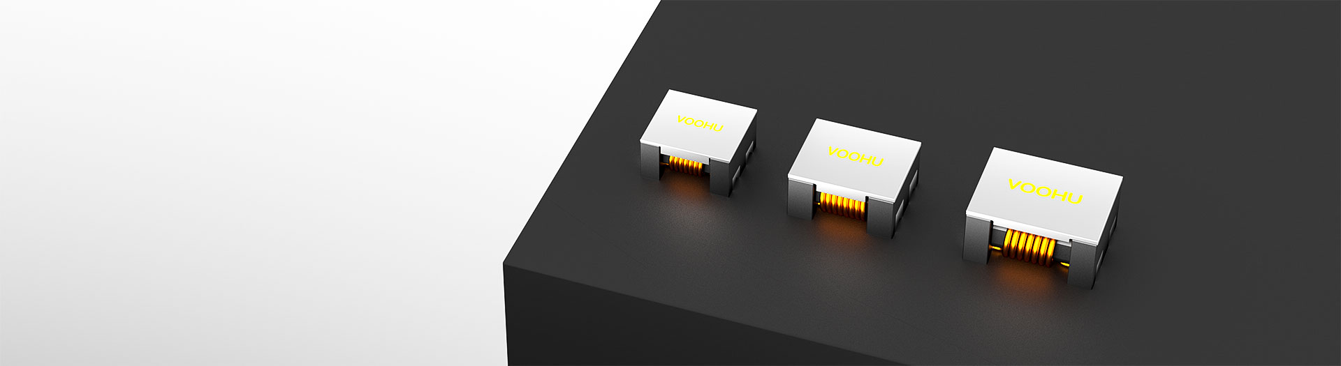
Inductor products
A common mode choke blocks noise that travels the same direction on both conductors while letting the supply current pass. Start from the frequency band your measurement actually fails, pick the impedance that covers it, then check rated current and DC resistance against the load the line has to carry.
Part number search & selector
The table uses the current English-site product records, published selection fields and part-specific technical-file links.
* Frozen Image and Part Number columns · drag horizontally to review all specifications
| Image | Datasheet | Compare | Downloads |
Dimensions(L*W*H MAX)
|
Z(Ω) 100MHz/0.1V Min.
|
Z(Ω) 100MHz/0.1V Ref.
|
DC Resistance (mΩ) Max.
|
Rated DC Current (A)Max.
|
Insulation Resistance (MΩ)Min.
|
Rated Voltage (V)Max.
|
Sample |
|---|
| Image | Part number | Datasheet | Compare | Downloads | Dimensions(L*W*H MAX) | Z(Ω) 100MHz/0.1V Min. | Z(Ω) 100MHz/0.1V Ref. | DC Resistance (mΩ) Max. | Rated DC Current (A)Max. | Insulation Resistance (MΩ)Min. | Rated Voltage (V)Max. | Sample |
|---|---|---|---|---|---|---|---|---|---|---|---|---|
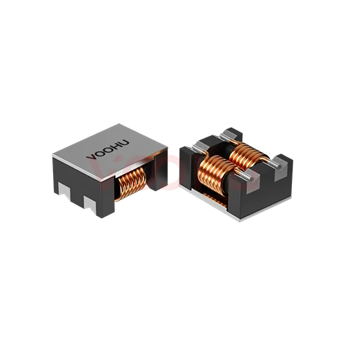 |
WHACM07A40R302 | SPEC | 7060 | 2500 | 3000 | 75 | 0.9 | 10 | 125 |
|
||
|
|
WHACM07A40R272 | SPEC | 7060 | 2000 | 2700 | 63 | 1 | 10 | 125 |
|
||
|
|
WHACM07A40R132 | SPEC | 7060 | 910 | 1300 | 21 | 2.5 | 10 | 125 |
|
||
|
|
WHACM07A40R102 | SPEC | 7060 | 800 | 1020 | 17 | 3 | 10 | 125 |
|
||
|
|
WHACM07A40R501 | SPEC | 7060 | 275 | 450 | 10 | 5 | 10 | 125 |
|
||
|
|
WHACM07A40R301 | SPEC | 7060 | 225 | 300 | 10 | 5 | 10 | 125 |
|
||
|
|
WHACM07A40R400 | SPEC | 7060 | 40 | 70 | 5 | 15 | 10 | 125 |
|
||
|
|
WHACM07A40R101 | SPEC | 7060 | 100 | 140 | 10 | 9 | 10 | 125 |
|
Broaden the selected filters or clear the current search.
Is this another brand's part number? Find the VOOHU replacement →
By series
Families differ in construction and size band, which sets impedance and current together.
How to select
Start from the conducted emissions failure, then work outward to current, DC resistance, voltage rating and footprint, in that order.
Read the conducted emissions scan and note where it crosses the limit. CISPR conducted limits typically run from 150 kHz to 30 MHz, and the band that fails tells you which part of the impedance curve the choke has to cover.
The selector quotes impedance at 100 MHz. Open the datasheet curve and read each candidate at your failing frequency instead, because a high 100 MHz figure says little about the part at 1 MHz.
Rated DC current must cover the worst-case load with margin for ambient. DCR sets the voltage drop and the copper loss. The rated voltage, 50, 80 or 125 V maximum on the listed parts, has to exceed the line it sits on.
Check the size code, land pattern and clearance, place the choke where the supply enters the board, and repeat the conducted scan on the real assembly with the full EMI filter fitted.
Parameters
Every column in the selector is defined under a stated condition. The impedance columns, for example, are measured at 100 MHz and 0.1 V, not at the frequency where your scan fails.
The table gives a minimum and a reference value measured at 100 MHz and 0.1 V. Use them to rank candidates on equal terms, then read the datasheet curve at your own failing frequency.
The maximum continuous DC current the winding carries, from 0.9 A to 15 A across this listing. Derate for ambient temperature and restricted airflow in the enclosure.
Listed as a maximum, from 2 to 80 milliohm across the range. Multiply by the load current for the voltage drop on the rail, and by the current squared for the heat the winding has to shed.
Maximum line voltage of 50, 80 or 125 V depending on series. Treat it as a hard limit for the working voltage; it is not a safety withstand rating, so check isolation requirements separately.
At least 10 megohm between the windings on every listed part. It confirms the two windings are separate conductors; it does not replace any withstand test your equipment standard calls for.
The uncoupled share of the winding behaves as a small differential mode inductor. With an X capacitor it adds some differential filtering. The selector does not list it, so read it from the datasheet if you rely on it.
Compare
The size code tracks current capability: the 4520 parts reach the highest impedance at currents up to about 3 A, while the 1513 parts carry up to 13 A with DCR down to about 5 milliohm.
Return to the selector ↑| Dimensions(L*W*H MAX) | Parts | Z(Ω) 100MHz/0.1V Min. | Z(Ω) 100MHz/0.1V Ref. | DC Resistance (mΩ) Max. | Rated DC Current (A)Max. | Insulation Resistance (MΩ)Min. | Rated Voltage (V)Max. | Action |
|---|---|---|---|---|---|---|---|---|
| 1211 | 7 | 80, 500, 600, 750, 2200, 2300 | 230, 700, 800, 1000, 2500, 2700 | 2, 4, 6, 8, 14, 35, 50 | 1.5, 1.8, 6, 8, 10 | 10 | 125 | Filter → |
| 1513 | 5 | 225, 400, 500, 800, 1200 | 300, 500, 700, 1000, 1500 | 5, 6, 7, 10, 23 | 5, 9, 10, 13 | 10 | 80 | Filter → |
| 4520 | 14 | 60, 90, 180, 200, 250, 300, 350, 500, 650, 800, 1000, 1200, 1800, 2500 | 90, 150, 230, 300, 380, 420, 500, 700, 900, 1000, 1200, 1400, 2000, 3000 | 35, 40, 45, 50, 55, 58, 60, 70, 80 | 1, 1.5, 1.9, 2.0, 2.1, 2.2, 2.4, 2.5, 3, 3.2 | 10 | 50 | Filter → |
| 7060 | 8 | 40, 100, 225, 275, 800, 910, 2000, 2500 | 70, 140, 300, 450, 1020, 1300, 2700, 3000 | 5, 10, 17, 21, 63, 75 | 0.9, 1, 2.5, 3, 5, 9, 15 | 10 | 125 | Filter → |
| 9070 | 6 | 225, 450, 500, 750, 1700, 2500 | 300, 600, 700, 1000, 2200, 3000 | 6, 8, 10, 13, 60, 75 | 2.5, 3, 4, 5, 5.5, 6 | 10 | 50 | Filter → |
Application review
Each review lists what to confirm before the choke is frozen in the BOM: line voltage, load current, the failing band and the space the filter may take.
Documents
Each power line common mode choke datasheet carries the impedance curve over frequency, the current rating, the outline drawing and the recommended land pattern.
Showing representative available file sets. Search to find a specific SKU.
VOOHU’s published product content is reviewed by its engineering team. Specifications, downloads and technical support information are tied to specific part numbers, so you can verify them before requesting samples or a quotation.
Category overview
A power line common mode choke (CMC) is the inductive half of most supply-side EMI filters. The notes below cover how it separates noise from load current, what the core material changes, and how it works with the capacitors around it.
Load current flows out on one conductor and back on the other, so inside the choke its two magnetic fields cancel and the part adds little more than its DC resistance. Noise that travels the same direction on both conductors and returns through ground or chassis sees the full inductance of the winding instead. That is how the same part blocks conducted emissions without dropping the supply.
The same component is often listed as a common mode inductor in inductor-centred catalogues, and older drawings may call it a common mode coil. Supply-side parts are also sold simply as a power line choke. Whatever the label, compare the impedance curve, the rated current and the rated voltage rather than the name on the datasheet cover.
Core material shapes the impedance curve. A ferrite core is the usual choice for compact parts and covers much of the conducted band. A nanocrystalline core has higher permeability and saturation flux density, so it can reach a given impedance at lower frequency in a smaller core, which is one reason it appears in large inverter and charger filters.
Construction matters as much as material. A toroidal common mode choke winds both conductors on a closed ring, which keeps the magnetic path short and suits high impedance at moderate current. An SMD common mode choke gives up some impedance per unit of board area in exchange for reflow assembly and a lower profile. The selector table does not list core material or winding style, so confirm both in the datasheet of each series.
A power line common mode choke rarely works alone. Y capacitors from each line to ground give common mode current a short return path, and the choke's impedance in series with them sets the attenuation. On mains-powered equipment, Y capacitor values are capped by touch-current limits, which is often why the choke has to supply most of the common mode attenuation. X capacitors across the line, together with the choke's leakage inductance, handle differential mode noise.
Picking a common mode choke for EMI filter work therefore means evaluating the network: change one part and the corner frequencies of the whole filter move. Layout, the position of the filter relative to the noise source and the ground return path all change the reading, so the final check is a CISPR-style conducted emissions scan on the real board in the real enclosure.
FAQ
Short answers on impedance, current margin, voltage rating, core material and how to request a part.
It winds both supply conductors on one shared core. Load current flows out on one conductor and back on the other, so the two fields cancel and the choke is nearly invisible to the supply. Common mode noise flows the same direction on both conductors, its fields add, and the choke presents a high impedance that keeps it off the line.
100 MHz is a common reference point that lets parts be compared on equal terms, and the selector uses it for both the minimum and the reference columns. Conducted emissions under CISPR limits are usually measured from 150 kHz to 30 MHz, so open the datasheet curve and read each candidate at the frequency where your scan fails.
The terms overlap in everyday use, but a common mode filter usually means the whole network, including Y capacitors and sometimes a differential inductor, while the choke is one component in it. Specify the choke as a part; design the filter as a stage, because its parts interact.
Check the rated voltage first. The parts listed here are rated at 50, 80 or 125 V maximum, which suits DC rails and low-voltage lines. Do not use a part above its rated voltage, and confirm insulation and safety requirements against the standard that applies to your equipment. For a mains-voltage EMI choke, ask the FAE team which options exist.
Size the rated DC current against the worst-case continuous load at the highest ambient inside the enclosure, not against the typical load at room temperature. Exceeding it drives temperature rise past what the part was rated for, and at high load current the leakage flux can push a ferrite core toward saturation, where the impedance falls and filtering suffers.
A toroidal choke generally offers more impedance and current per unit cost, at the price of board area, height and often hand assembly. An SMD part suits reflow assembly and tight boards. Start from the impedance and current you need, then let the mechanical constraints decide, and check the construction in the datasheet of each series.
When you need high common mode impedance at low frequency, typically in the lower part of the conducted band, and the board cannot take a large ferrite core. Nanocrystalline material reaches that impedance in a smaller core, which is why it is common in inverter and charger filters. Check the core material in the datasheet; the selector table does not list it.
VOOHU is the common mode choke manufacturer for the parts on this page and makes its magnetics in its own factory in Mianyang. Datasheets are linked from each part number. For samples or a quote, send the part number, quantity and the date you need it; if you are still selecting, send the line voltage and current, the failing band and the board space. Samples are available for evaluation, and selected parts are free of charge. Our FAE team will be glad to confirm the options for your project.
Engineer support
Send the candidate part number and the condition you need reviewed. Sample support can be added after the selection is clear; commercial questions may be discussed in the same engineering conversation.
Include the document revision
Temperature, isolation voltage and PoE current basis
Pin count, pitch and spacing between pin rows
To help prioritize samples and evaluation
When you need candidates and a comparison of differences
Engineering review identifies candidate parts and explains the differences.
From the selector or engineering review
Prototyping / pilot build / production
Specify sample and production timing separately
Compliance documents, material declarations or third-party reports
Samples are available for evaluation, and selected parts are free of charge. Our FAE team will be glad to confirm the options for your project. Sales will respond on business days.