Size
Use this published field to confirm package and board-level mechanical fit.
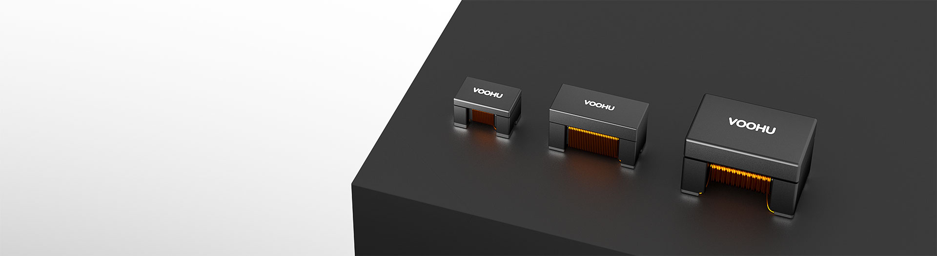
Transformer products
Select chip LAN magnetics for compact Ethernet interfaces. VOOHU offers WHLT chip LAN transformers and WHLC companion components for different data-rate and power requirements. Start with the component function, then compare parts against your PHY, electrical requirements and PCB constraints. Already have a part number? Ask about samples, availability and pricing.
Part number search & selector
The table uses the current English-site product records, published selection fields and part-specific technical-file links.
* Frozen Image and Part Number columns · drag horizontally to review all specifications
| Image | Datasheet | Compare | Downloads |
Size
|
Classification
|
Data Rate
|
L(μH)
|
Impedance(Ω)
|
PoE
|
Sample |
|---|
| Image | Part number | Datasheet | Compare | Downloads | Size | Classification | Data Rate | L(μH) | Impedance(Ω) | PoE | Sample |
|---|---|---|---|---|---|---|---|---|---|---|---|
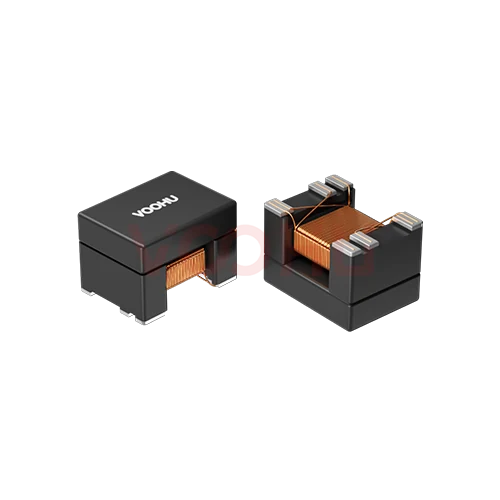 |
WHLT-4532E-201MGN | SPEC | 4532E | X‘fmr+CMC | 100/1000 BASE-T | 200 @8mA DC BIAS | - | Non-PoE |
|
Broaden the selected filters or clear the current search.
Product family quick links
Counts reflect the current published product data.
How to select
Narrow the published fields in sequence, compare the remaining candidates and verify the part-specific files before design-in.
Distinguish a transformer, a common mode choke and a complete coupling network. The CHIP LAN label alone is not a selection criterion.
Record the PHY model, port count, target data rate and PoE or non-PoE requirement. One chip-format component is not necessarily a complete set of port magnetics.
Compare OCL together with test frequency, voltage and DC bias. Compare common mode impedance at the stated frequency. Common mode impedance is not the Ethernet differential impedance, and OCL bias current is not a PoE current rating.
Check pin assignments, winding connections, recommended land pattern, isolation paths and reflow requirements for the exact part, then validate signal and EMC performance in the target circuit.
Key selection parameters
Use this published field to confirm package and board-level mechanical fit.
Use this published parameter to narrow the candidate part numbers before datasheet review.
Use this field to align the part family with the required interface or connection.
Use this published parameter to narrow the candidate part numbers before datasheet review.
Compare the published values with the electrical limits required by the design.
Compare the published values with the electrical limits required by the design.
Product family comparison
Use this summary as a routing step, then verify every required value in the exact part-number row and linked technical files.
Return to the selector ↑| Size | Parts | Classification | Data Rate | L(μH) | Impedance(Ω) | PoE | Action |
|---|---|---|---|---|---|---|---|
| 2012(0805) | 8 | Cap+CMC | 100/1000 BASE-T | - | 90, 180, 260, 360, 380, 800, 1000, 1200 | Non-PoE | Filter → |
| 3216(1206) | 2 | Cap+CMC | 100/1000 BASE-T, 2.5G/5G Base-T | 55, 60 | - | Non-PoE | Filter → |
| 3532A | 3 | X‘fmr+CMC | 100/1000 BASE-T, 2.5G/5G Base-T, 10G Base-T | 120 @10.5mA DC BIAS, 200 @8mA DC BIAS, 150 @8mA DC BIAS | - | Non-PoE, PoE af | Filter → |
| 4532B | 7 | X‘fmr+CMC | 100/1000 BASE-T, 2.5G/5G Base-T, 10G Base-T | 120 @10.8mA DC BIAS, 120 @15mA DC BIAS, 150 @10.5mA DC BIAS, 180 @10.5mA DC BIAS, 200 @8mA DC BIAS, 350 @8mA DC BIAS | - | Non-PoE, PoE af, PoE at | Filter → |
| 4532E | 1 | X‘fmr+CMC | 100/1000 BASE-T | 200 @8mA DC BIAS | - | Non-PoE | Filter → |
| 5335A | 2 | X‘fmr+CMC | 2.5G/5G Base-T, 10G Base-T | 120 @15.75mA DC BIAS, 150 @21mA DC BIAS | - | PoE at, PoE bt | Filter → |
Technical performance & application fit
Application suitability is part-number specific. Treat the catalog fields as a shortlist, then confirm the design against the linked technical files.
Downloads & technical resources
Search a full or partial SKU, then open its datasheet, 3D model or PCB footprint without returning to the product table.
Showing representative available file sets. Search to find a specific SKU.
VOOHU’s published product content is reviewed by its engineering team. Specifications, downloads and technical support information are tied to specific part numbers, so you can verify them before requesting samples or a quotation.
Category overview
Surface mount magnetics for Ethernet come in two related forms, and knowing which one a part number is saves a lot of confusion.
Discuss a new design
Contact FAE for a replacement assessment.
Already have a part number? Request samples or a quote.
A chip LAN transformer provides the isolation and signal coupling the Ethernet port needs. A companion common mode choke is a separate part that improves common mode rejection alongside it. Some designs use both. Read what the part actually is first, because the two are specified differently.
Codes such as 2012, 3216 and 4532 describe the footprint, and they make a useful first cut when board area is constrained. They say nothing about speed rating, PoE capability or insertion loss. Two parts in the same package can be specified for very different links, so always read the electrical data.
As with any Ethernet magnetics, the link speed sets the signal integrity requirement and the PoE class sets the bias current the part has to tolerate. A compact package does not relax either constraint. Filter on speed and PoE first, then use package size to narrow what remains.
FAQ & related guides
These answers guide the page workflow. Part-specific engineering limits still come from the linked technical files.
No. A chip LAN transformer in this catalog is a passive magnetic component. The PHY IC handles Ethernet physical-layer transmission and reception. They are not interchangeable. Check the part number, schematic and component function so that a transformer search does not turn into an Ethernet-controller IC selection.
A transformer couples signals and provides the isolation performance specified for its construction. A common mode choke primarily suppresses common mode noise. A choke alone is not a complete Ethernet isolation transformer. Even when both appear under CHIP LAN, confirm their separate BOM roles and surrounding circuits rather than assuming all functions are integrated in one package.
Start with the PHY model, target data rate, PoE requirements and available PCB space. Compare candidate parts for OCL, bias conditions, loss specifications and pin assignments. For Gigabit, 2.5G, 5G or 10G designs, select a version explicitly covered by the datasheet and validate samples in the intended circuit.
There is no single answer for the whole category. The catalog includes non-PoE parts and parts intended for PoE applications. Check the exact part, power standard, current definition and thermal conditions. PoE+ and PoE++ can describe your project requirements, but they are not per-transformer power guarantees. The milliamp bias used in an OCL test is not a power-delivery current rating.
Matching speed or appearance does not establish a drop-in replacement. A conventional module may contain multiple transformers and common mode chokes. A discrete magnetics design also requires review of companion components, pins, routing, isolation and PoE conditions. Send the current part or schematic so FAE can identify candidates and explain differences before sample validation.
No universal circuit should be assumed. Review the coupling capacitors, companion magnetics, PHY interface and protection network against the specific reference design. A capacitor voltage rating does not establish system isolation. This page does not prescribe a capacitor value, component placement or isolation threshold for every part. Share your PHY and application conditions for an appropriate evaluation path.
If you have a part number, share it with the quantity, project stage, destination and requested dispatch date. Pricing depends on the part and quantity; sales will confirm availability and lead time. If no part has been selected, start with the application and target speed. For a replacement request, attach the existing-part documentation—you do not need to complete the comparison yourself first.
Download files for the same part number and check their revisions. Use the datasheet for electrical conditions and winding connections, the dimension drawing and footprint for pads and orientation, and the relevant reflow profile for the process window. If files are missing or revisions conflict, ask an engineer before substituting documentation from another family.
Engineer support
Send the candidate part number and the condition you need reviewed. Sample support can be added after the selection is clear; commercial questions may be discussed in the same engineering conversation.
Include the document revision
Temperature, isolation voltage and PoE current basis
Pin count, pitch and spacing between pin rows
To help prioritize samples and evaluation
When you need candidates and a comparison of differences
Engineering review identifies candidate parts and explains the differences.
From the selector or engineering review
Prototyping / pilot build / production
Specify sample and production timing separately
Compliance documents, material declarations or third-party reports
Sample quantity, lead time and cost depend on the project stage and part number. Sales will respond on business days.